5 wiring – PowerMax DE5450 User Manual
Page 5
DE5450
5
panel from the bracket will start a tamper alarm. Forcibly
removing the entire assembly off the wall will also start a
tamper alarm, because the joints of the ring and cam
piece to the bracket leg will break off, leaving the ring and
cam attached to the wall.
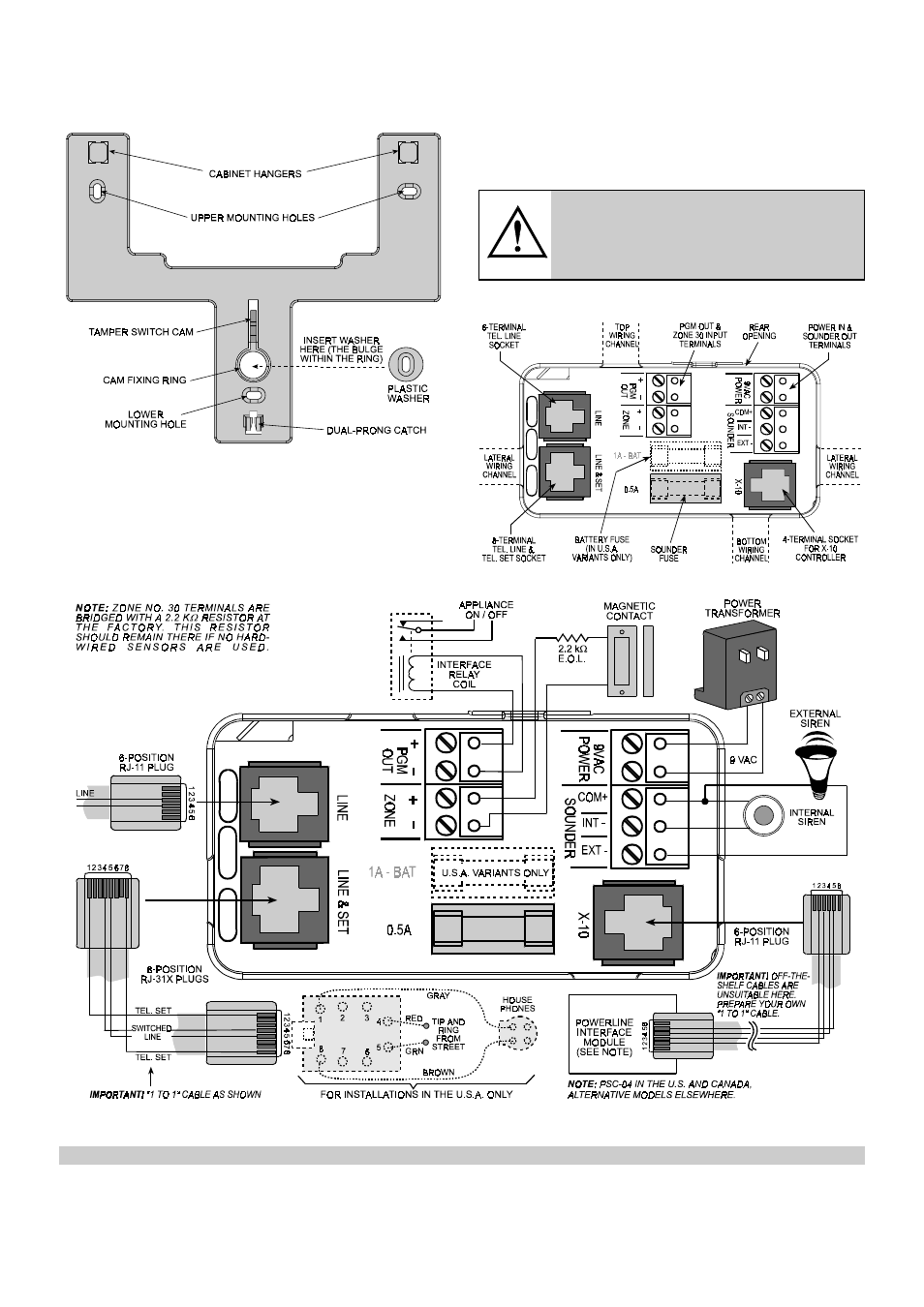
Figure 8. Bracket - Front View
C. Attaching the Bracket to the Wall
Choose a concealed place, yet easily accessible to
prospective users of the alarm system. Make sure that an
uninterrupted AC power outlet and a telephone line socket
are available near the installation spot.
Use the bracket as a template to mark the drilling points.
Drill the holes and attach the bracket to the wall with 4
screws. Be sure to insert the special plastic washer into
the ring, as shown in Figure 8.
3.5 Wiring
All terminals and connectors are accessible within the
opening at the back of the PowerMax (see Figure 9). All
screw terminal blocks can be pulled out, wired
appropriately and plugged back in.
WARNING! When plugging terminals back
into place, be sure to align them carefully
with the pins on the PCB. Mis-aligned or
reverse insertion of terminals may damage
internal PowerMax circuits!
The telephone-type connectors are also easy to deal with,
because of their quick attach/detach capability.
Figure 9. Sunken Wiring Area Layout
Figure 10. Wiring Diagram
CAUTION: The sounder and PGM outputs can not be used in UL-listed installations