Lennox Hearth B-Vent Elite LBV-3824MP-H User Manual
Page 7
7
NOTE: DIAGRAMS & ILLUSTRATIONS NOT TO SCALE.
Figure 11
Step 5. Field Wiring – Refer to Section A for
millivolt appliances and Section B for electronic
appliances.
A. Millivolt Wiring – Units may be fitted at the
factory with either a Honeywell millivolt gas
control valve or an SIT millivolt gas control
valve. Both valves have been tested with and
approved for use with these appliances and are
listed accordingly. Refer to
Figure 13 for
wiring of Honeywell systems and
Figure 14 for
wiring of SIT systems.
The gas valve has been set in place and has been
pre-wired at the factory. No additional wiring is
required unless the optional wall switch or op-
tional remote control kit is to be installed. Locate
the optional wall switch or optional remote con-
trol in the desired location and connect the
millivolt wire
(see Figures 13 and 14 ).
CAUTION: DO NOT CONNECT THE WALL
SWITCH TO A 120V POWER SUPPLY.
Step 4. Install the Vent System & Exterior
Termination -
A - Connect the factory-supplied B-Vent con-
nector (found taped to the top of the unit) as
shown in
Figure 11. Press it into the lanced
protrusions internal to the flue outlet collar as
far as the horizontal rolled seam located on the
lower part of the connector, and secure with
four sheetmetal screws (# 8 or larger).
B - Slip an 8" (203 mm) B-Vent system over
the B-Vent connector and secure with four
sheetmetal screws (# 8 or larger), and install
the remainder of the B-Vent to the outside.
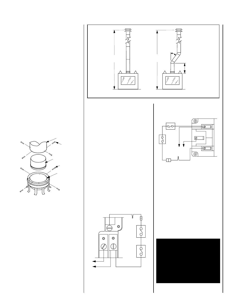
Minimum overall height of the vent system
and appliance must be 12' (3.66 m) vertical
(no offset) or 17' (5.18 m) when an offset up
to 45 degrees from the vertical is used. The
lower part of the offset must not begin less
than 3' (0.914 m) above the top of the fireplace
(see Figure 12 ).
Maximum overall height of the vent system and
appliance should not exceed 40 feet (12.19m).
Figure 12
Figure 13
Note: Optional wall switch not supplied. If the
optional wall switch is not installed, the ends
of the 18' coiled wire must be connected with
a wire nut (not supplied) for the appliance to
operate.
B. Electronic Wiring – The electronic appli-
ance must be connected to the main power
supply. To install, route a 3-wire 120V 60Hz
power supply to the appliance junction box
and ground. Locate and install a low voltage
(24V) wall switch (not supplied) in the desired
location. Connect the low voltage wire to this
switch
(see Figure 15 on Page 8 ).
Install the B-vent system in accordance with
the vent manufacturer's instructions.
CAUTION: THIS APPLIANCE CANNOT BE
VENTED HORIZONTALLY.
Note: Refer to the vent manufacturers instal-
lation instructions for variations of venting
techniques. If common venting of several units
is contemplated, it should be discussed with
an architect and the local Building Depart-
ment.
Figure 14
12 ft.
Minimum
17 ft.
Minimum
45 degrees
max.
3 ft.
Minimum
to Offset
Thermopile
Damper
Switch
TH
TP
TH
TP
Honeywell Millivolt Wiring Diagram
If any of the original wire as supplied must be replaced,
it must be replaced with
Type AWM 200
°
C – 18 GA. wire.
TH
TPTH
T P
* For Wall Switch Attachment Only.
*
Limit
Switch
BK
BK
BK
BK
WT
SIT Millivolt Wiring Diagram
* For Wall Switch Attachment Only.
If any of the original wire as supplied must be replaced,
it must be replaced with
Type AWM 200
°
C – 18 GA. wire.
Thermopile
TH
TP
TH
TP
Limit
Switch
Damper Switch
BK
BK
BK
BK
WHT
*
8”
Type B-Vent
Lanced Flue
Outlet Collar
Factory-Supplied
B-Vent Connector
Securing
Screws
Securing
Screws
IMPORTANT: Ground lead must be connected
to the green screw located on the outlet box.
See
Figure 18 on page 9. Failure to do so will
result in a potential safety hazard. The ap-
pliance must be electrically grounded in
accordance with local codes or, in the ab-
sence of local codes, the National Electrical
Code, ANSI/NFPA 70-(latest edition). (In
Canada, the current CSA C22-1 Canadian
Electrical Code.)