Lennox Hearth B-Vent Elite LBV-3824MP-H User Manual
Page 10
10
NOTE: DIAGRAMS & ILLUSTRATIONS NOT TO SCALE.
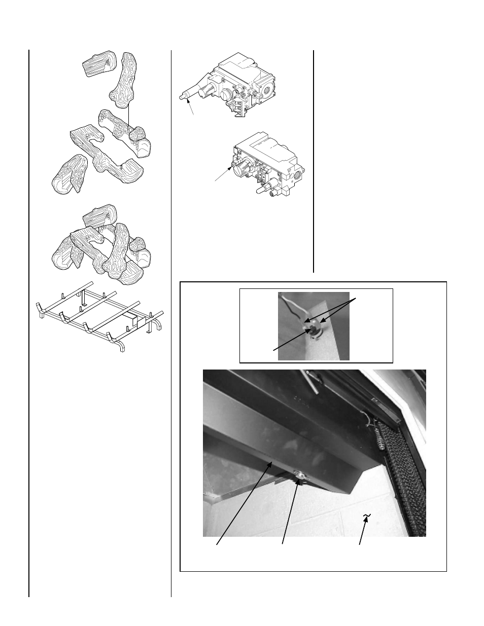
Figure 19
Figure 20
When first lighting the appliance, it will take a
few minutes for the line to purge itself of air.
Once purging is complete, the pilot and burner
will light and operate as indicated in the in-
struction manual.
Refer to the Homeowners Care and Operation
Instructions for detailed log description and
placement instructions. Log set shown in this
document
(Figure 19) is typical, installation of
all sets are similar.
APPLIANCE OPERATION
Step 9. Checking the System – With gas line
installed run initial system checkout before
closing up the front of the unit. Follow the pilot
lighting instructions provided in the
Homeowner's Care and Operation Instructions.
For piezo ignitor location see
Figure 20 (milli-
volt appliances only).
Note: Instructions are also found on the pull out
lighting instructions label attached to the gas
control valve.
Piezo Ignitor
Piezo Ignitor
SIT Valve
Honeywell Valve
Typical Log Set
(Refer to Owners
Manual for Details)
Subsequent lightings of the appliance will
not require such purging. Inspect the pilot
flame (remove logs, if necessary, handling
carefully).
MANUALLY-RESET BLOCKED FLUE SAFETY
SWITCH
This appliance is equipped with a manually-
reset blocked flue safety switch. Refer to
Figure 21 for its location. If during appliance
operation, the flame goes out (independently
of the burner on/off wall switch), it may be due
to the operation of this safety limit switch.
First allow the appliance to cool. Then reset
the safety switch by pushing the red reset
button.
This reset button is located on the back of the
limit switch, between the wire terminals (
see
Detail A of Figure 21 ).
The appliance should then relight and remain
lit. If this does not occur, turn off the appli-
ance and call a qualified service technician.
Figure 21
Manual Reset
Limit Switch
Lintel
Extension
Right Side
Refractory Panel
Reset
Button
Wire
Terminals
Detail A