Troubleshooting & repair, Main transformer (t1) voltage test (continued), Warning – Lincoln Electric IDEALARC DC-655 User Manual
Page 68
TROUBLESHOOTING & REPAIR
F-26
F-26
IDEALARC DC-655
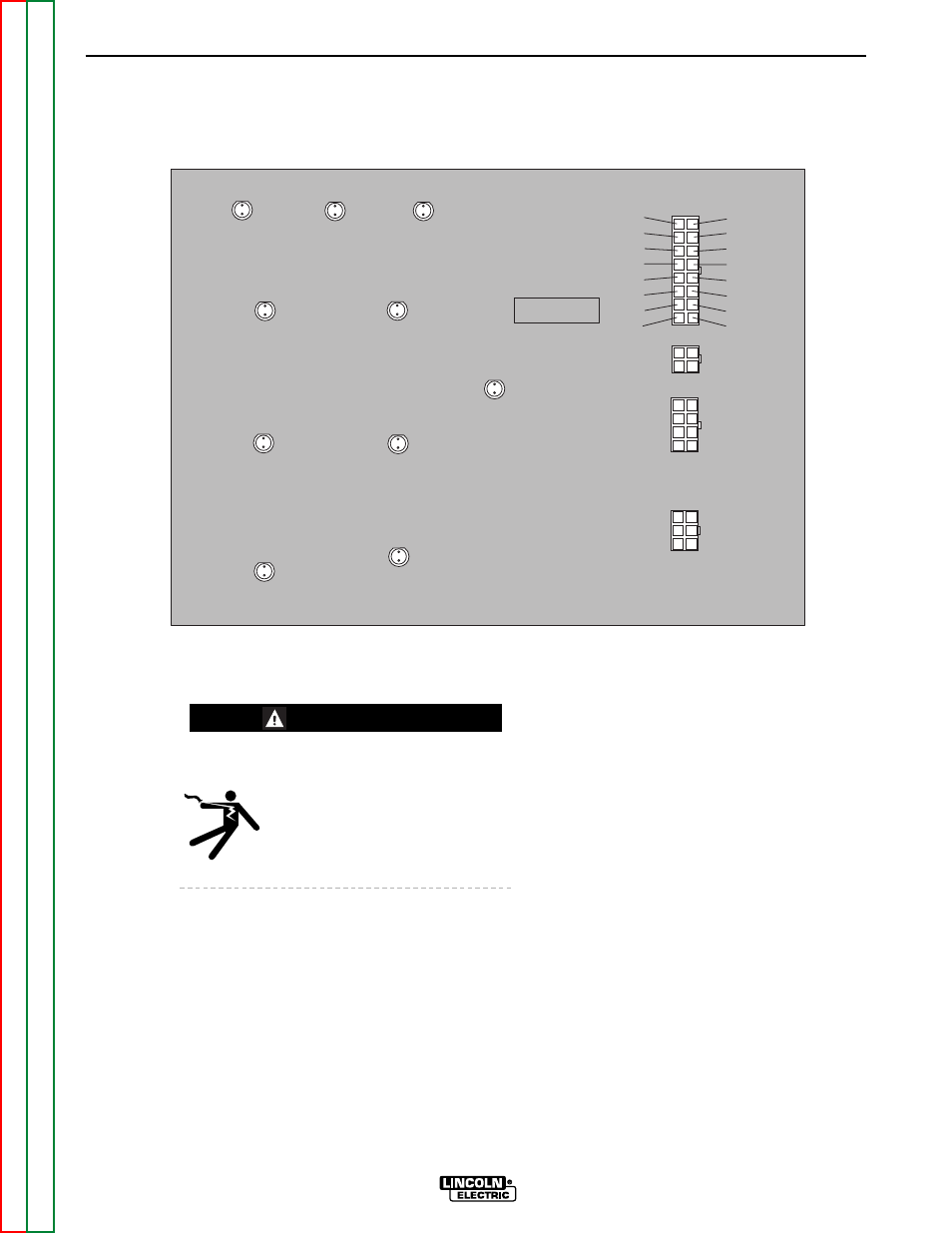
15. Locate plug J5 on the firing board. See
Figure F.9.
ELECTRIC SHOCK
can kill.
• Do not touch electrically hot
parts.
16. Turn on the DC-655 and check for approx-
imately 32 VAC at the following leads and
pins at plug J5. These are the phase angle
winding voltages. See Fig. F.9.
Plug J5 pin-15 (lead #203) to pin-16 (lead
#204)
Plug J5 pin-8 (lead #205) to pin-7 (lead
#206)
Plug J5 pin-6 (lead #207) to pin-5 (lead
#208)
17. Locate plug J13 on the optional digital
meter board. If a digital meter board is not
in place, plug J13 will not be used but will
be present in the harness. Check the fol-
lowing voltages at the appropriate leads
and pin locations.
10 VAC Plug J13 pin-1 (lead #331) to pin-2
(lead #332)
10 VAC Plug J13 pin-4 (lead #333) to pin-5
(lead #334)
42 VAC Plug J13 pin-3 (lead #335) to pin-6
(lead #336)
18. If the correct primary voltages are applied
to the main transformer and any of the sec-
ondary voltages are missing or not correct,
the transformer may be faulty.
NOTE: Always check the wiring between
the transformer windings and the test
points before replacing the transformer.
MAIN TRANSFORMER (T1) VOLTAGE TEST (continued)
FIGURE F.9 - FIRING BOARD PLUG J5 PINS
FIRING BOARD
G2699-[ ]
16 (204)
15 (203)
14
13 (231)
12 (215)
11
10
9
(205) 8
(206) 7
(207) 6
(208) 5
4
3
2
1
LED7
LED8
LED9
LED1
LED2
LED3
LED4
LED5
LED6
LED10
J5
J6
J7
J4
WARNING