Accessories – Lincoln Electric IDEALARC DC-655 User Manual
Page 26
NOTE: The connection diagram shown in Figure C.1
shows the electrode connected for positive
polarity. To change polarity:
a.
Set the Idealarc DC-655 POWER toggle
switch to the OFF (0) position.
b.
Move the electrode cable to the negative (-)
output terminal. (High inductance or low
inductance, as needed).
c.
Move the work cable to the positive (+) output
terminal.
d.
If connecting lead #21 to the terminal strip,
connect it to the +21 terminal (to match work
polarity). If work polarity changes back to
negative, lead #21 must be connected to the
-21 terminal.
e.
Reverse the leads on the back of the ammeter
and voltmeter in the automatic control box.
f.
If the automatic controls include a variable
voltage board, connect its jumper lead to pin
“L”. This will permit the inch down button to
operate. However, the jumper also disables
the cold starting/autostop feature of the auto-
matic controls. Only hot starting will be avail-
able.
6.
Set the DC-655 OUTPUT CONTROL switch to the
“Remote” position and the OUTPUT TERMINALS
switch in the “Remote” position.
CONNECTING THE NA-5/-5R TO THE
IDEALARC DC-655 (TERMINAL STRIP)
1.
Set the Idealarc DC-655 POWER toggle switch to
the OFF (0) position.
2.
Disconnect main AC input power to the Idealarc
DC-655.
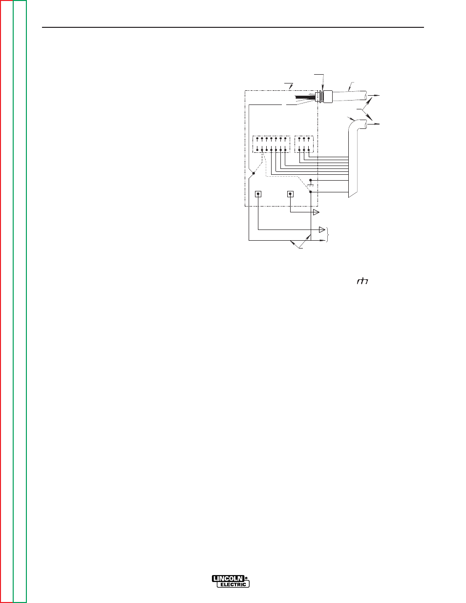
3.
Connect the wire feeder control cable leads to the
Idealarc DC-655 terminal strip as shown in Figure
C.2.
FIGURE C.2 – NA-5/-5R WIRE FEEDER
CONNECTION TO THE IDEALARC DC-655
4.
Connect the wire feeder control cable ground lead
to the frame terminal marked .
NOTE: The Idealarc DC-655 must be properly
grounded.
5.
Extend wire feeder control cable lead #21 so it can
be connected directly to the work piece.
a.
Make a bolted connection using AWG #14 or
larger insulated wire. Tape the bolted connec-
tion with insulating tape.
b.
An S-16586-X remote voltage sensing work
lead is available for this purpose.
c.
Keep the #21 lead electrically separate from
the work cable circuit and connection.
d.
Tape the #21 lead to work cable for ease of
use.
ACCESSORIES
C-4
C-4
IDEALARC DC-655
NEGATIVE
POSITIVE
32
31
2
4
GND
21
TO WORK
POWER SOURCE
21
FOR CONTROL CABLE
WITH 14 PIN
MS-TYPE
PLUG CONNECTOR
OR
FOR CONTROL CABLE
WITH TERMINAL STRIP
LEAD CONNECTORS
CONTROL CABLE
14-PIN
RECEPTACLE
A
B
C
INPUT CABLE PLUG
CONTROL CABLE
41 4 2 31 32
75 76 77
21
-
21
+
REMOTE VOLTAGE SENSING LEAD
TO NA-5/-5R
BOLT TO CABLES FROM NA-5/-5R
WIRE CONTACT AS'BLY