Accessories, Semiautomatic wire feeders – Lincoln Electric IDEALARC DC-655 User Manual
Page 28
SEMIAUTOMATIC WIRE FEEDERS
CONNECTING THE LN-7 TO THE IDEALARC
DC-655 (14-PIN MS RECEPTACLE)
1.
Set the POWER toggle switch to the OFF (0) posi-
tion.
2.
Disconnect main AC input power to the Idealarc
DC-655.
3.
Connect the electrode cable from the control
cable to the “+” terminal of the welder and to the
LN-7 wire feeder. Connect the work cable to the
“-” terminal of the welder (High inductance or low
inductance as needed). Reverse this hookup for
negative polarity.
NOTE: Welding cable must be sized for the current
and duty cycle of the application.
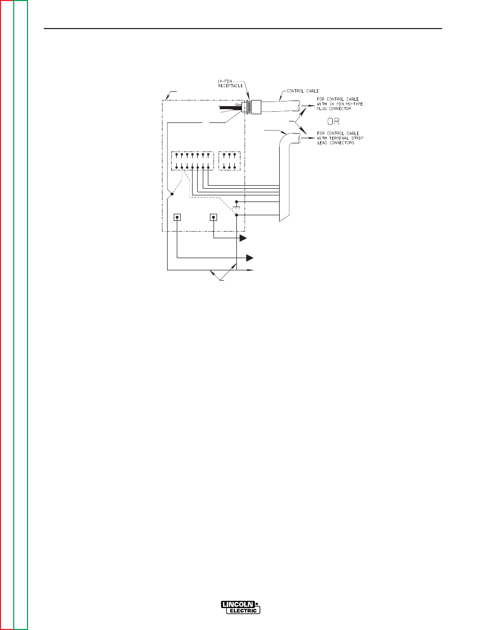
4.
Connect control cable between the DC-655 and
the LN-7. See Figure C.3.
5.
Set the MODE switch to a CV (constant voltage)
position at the welder.
6.
Adjust wire feed speed at the LN-7 and set the
welding voltage with the output CONTROL.
NOTE: If optional remote control is used, place the
OUTPUT CONTROL and the OUTPUT TERMI-
NALS switch in the “Remote” position.
ACCESSORIES
C-6
C-6
IDEALARC DC-655
41 4 2 31 32
75 76 77
NEGATIVE
POSITIVE
32
31
2
4
GND
21
ELECTRODE CABLE
TO WIRE FEED UNIT
TO WORK
}
POWER SOURCE
LN-7 TO INPUT
CABLE PLUG
LN-7 CONTROL
CABLE
21
-
21
21
+
REMOTE VOLTAGE SENSING LEAD
FIGURE C.3
IDEALARC DC-655/LN-7 WITH K584 INPUT CABLE ASSEMBLY CONNECTION DIAGRAM