Iswitch-front panel – Lindy iSWITCH User Manual
Page 5
5
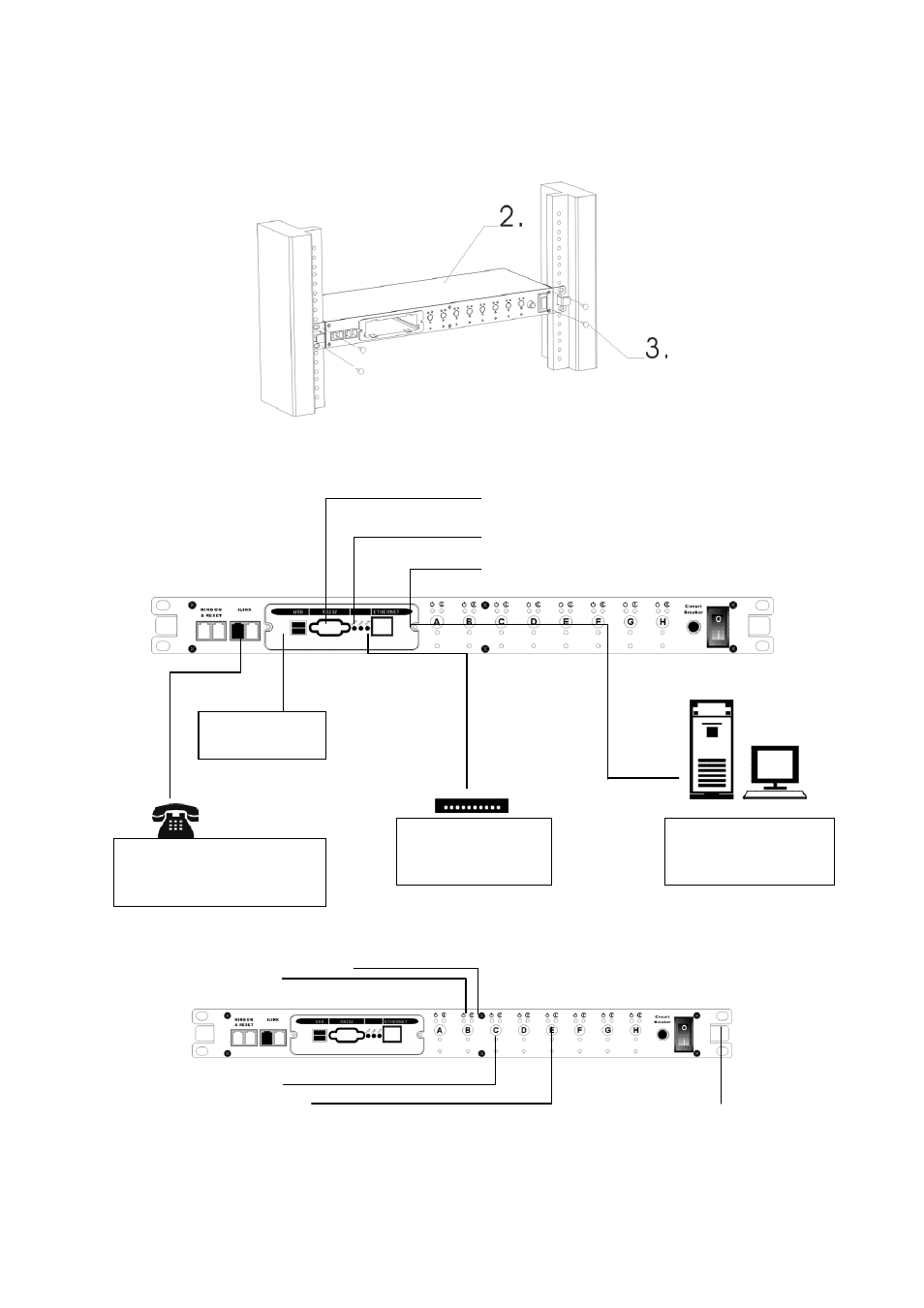
iSwitch-Front Panel
Setup
via
USB
Port
Setup via RS232 Port
Setup via Ethernet Port
Receptacle Control Status LED (Green)
Receptacle Status LED (Red)
Active Module LED (Yellow)
Momentary switch for Receptacle
Master Power Switch
iLink Port is for
Daisy Chaining
External Modem is
required for Pager
Function
Ring On/Reset Port –
Connect a telephone line to
control the iSwitch
Connect to the
network to control the
iSwitch
See also other documents in the category Lindy Computer Accessories:
- 32402 (35 pages)
- 25009 (2 pages)
- PRO-300 (28 pages)
- Switch (76 pages)
- Dual Rail Modular KVM Console Switch (20 pages)
- 32514 (71 pages)
- 32321 (12 pages)
- KVM 42339 (3 pages)
- 32927 (16 pages)
- 32595 (4 pages)
- 32416 (8 pages)
- 32361 (69 pages)
- MC5-IP (111 pages)
- 1:04 (2 pages)
- 32451 (2 pages)
- V1.21 (5 pages)
- CPU IP Access Switch Plus (64 pages)
- 39323 (2 pages)
- 42791 (5 pages)
- 32849 (9 pages)
- P16-IP (77 pages)
- 39122 (7 pages)
- 70539 (8 pages)
- 38000 (12 pages)
- 25004 (24 pages)
- KVM EXTENDER 32357 (10 pages)
- 25044 (2 pages)
- GIGAPATCHPANEL 20704 (12 pages)
- 25010 (63 pages)
- 42887 (4 pages)
- Webcam (43 pages)
- 25032 (2 pages)
- 51550 (20 pages)
- 32571 (8 pages)
- 32890 (2 pages)
- 25007 (2 pages)
- 40592 (2 pages)
- 32353 (81 pages)
- CAT5 (6 pages)
- 32591 (12 pages)
- L1TBELRG (51 pages)
- 25008 (18 pages)
- CPU SWITCH (38 pages)
- 32969 (2 pages)