Lennox Hearth LENNOX MPE-33R User Manual
Page 3
NOTE: DIAGRAMS & ILLUSTRATIONS NOT TO SCALE.
3
3
Installation must conform to local codes.
In the absence of local codes, electrical
wiring and grounding must comply with
the National Electrical Code ANSI/ NFPA
70 - latest edition. In Canada, the cur-
rent CSA C22-1 Canadian Electrical Code
- latest edition.
CONGRATULATIONS!
In selecting this LENNOX Merit Plus electric fi replace, you have chosen the fi nest and
most dependable fi replace found anywhere. A beautiful and prestigious addition to
the fi nest homes. Welcome to a Family of hundreds of thousands of satisfi ed LENNOX
Fireplace Owners.
Please read and carefully follow all of the instructions found in this manual. Please
pay special attention to the safety instructions provided in this manual. The instruc-
tions included here will assure that you have many years of dependable and enjoyable
service from your LENNOX product.
TABLE OF CONTENTS
Important Safety Information ........... Page 2
Packaging List .................................. Page 3
Introduction ..................................... Page 3
General Information ......................... Page 3
Locating Fireplace ............................ Page 3
Tools/Supplies Required .................. Page 3
Framing Specifi cations ..................... Page 4
Fireplace Specifi cations .................... Page 4
Clearances ....................................... Page 5
Pre-installation ................................. Page
5
Installation Steps ............................. Page 5
Electrical Connections ...................... Page 5
Final Finishing .................................. Page 6
Break-In Period ................................ Page 6
Control Panel Operation ................... Page 6
Remote Control Operation ............... Page 7
Maintenance ..................................... Page
8
Wiring Diagrams .............................. Page 10
Troubleshooting ............................... Page 15
Replacement Parts ........................... Page 16
Optional Accessories ........................ Page 18
PACKAGING LIST
This assembled Electric Room Heater is
packaged with:
• One accessory package located in the
fi rebox, containing;
1. One Installation and Operation Manual.
2. One Warranty Certifi cate.
3. One Remote Control.
• Two spare Light Bulbs are located in a
recess on the back of the log assembly.
INTRODUCTION
This Electric Fireplace is designed for
residential applications to be framed in
as a fi replace.
This appliance has been tested in accor-
dance with UL 2021 and CSA C22.2 No.
46-M198 standards for fi xed and location
dedicated electric room heaters.
WARNING
Do not install or operate this fi re-
place through a switch wired in the
120 VAC or 240 VAC circuits. The
only approved wiring for a switch
is through the low voltage circuit
(24 VAC) as shown on Page 14.
GENERAL INFORMATION
Power Supply Wire Specifi cations
120 Volt, 60 Hz, 1600 Watts:
(ref. Page 10)
Hard Wire Connection - Use two conductor,
non-metallic sheath cable with ground wire
(total three wires) for the incoming power
supply. The wire used must conform to local
and national electrical codes for the specifi ed
power consumption rating. See Table 1.
240 Volt, 60 Hz, 3000 Watt:
(ref. Page 11)
Use three conductor, non-metallic sheath cable
with ground wire (total four wires) for the
incoming power supply. The wire used must
conform to local and national electrical codes
for the specifi ed power consumption rating.
See Table 1.
Wall Switch or Wall Thermostat Kits
(optional kits, see Page 17)
Low voltage wire is provided for the wall switch
connection. The wires gage requirements are
shown on Table 1.
Power Supply Wire Gage
Voltage
Wire Gage
Fuse
120 V
14 GA.
15 AMP
240 V
14 GA.
20 AMP
Wall Switch / Thermostat Wire Gage
Voltage
Wire Gage
5 VOLTS
18 GAGE
Table 1
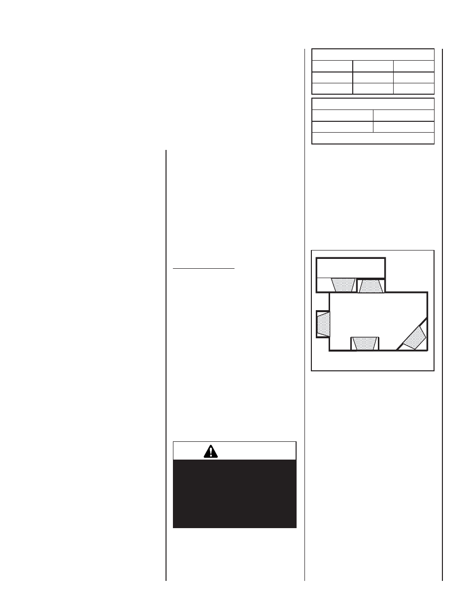
Figure 1
LOCATING YOUR MERIT PLUS ELECTRIC
FIREPLACE
Your new fi replace may be installed into existing
framing or built into a wall (see Figure 1).
When choosing a location for your new fi re-
place, ensure that the general instructions are
followed. Also, for the best effect, install the
fi replace out of direct sunlight and away from
overhead lighting. See Figure 1.
fi replace shown in gray.
TOOLS AND BUILDING SUPPLIES
NORMALLY REQUIRED
TOOLS:
Phillips Screwdriver
7/16" Socket Drive
Hammer
Saw And/or Saber Saw
Level
Measuring Tape
Plumb Line
Electric Drill And Bits
Pliers
Square
Gloves
IMPORTANT NOTE: This fi replace system
is not diffi cult to install. However, in the
interest of safety, it is recommended that
the installer be a qualifi ed or certifi ed
“tradesman” familiar with commonly
accepted fi replace installation and safety
techniques as well as prevailing local
codes.
BUILDING SUPPLIES:
Framing Materials
Wall Finishing Materials
Caulking Materials
(noncombustible)
Top View Showing Approved
Room Locations of Fireplace