Lochinvar RPV-I&S User Manual
Page 7
7
RPV-I&S
NOTE: For installations requiring both horizontal and vertical runs,
the following rule must be followed: Total number of feet of straight
pipe (both horizontally and vertically) must not exceed the allowable
length listed in the “Through The Wall” section of the table for total
number of elbows used. Also: Total number of vertical feet of straight
pipe must not exceed the allowable length listed in the “Through The
Roof” section of the table for total number of elbows used. For
angular rises in venting, any angle that is greater than or equal to
45° from the horizontal should be considered a vertical rise.
HIGH ALTITUDE INSTALLATIONS FOR ELEVATIONS OVER 2,000 FEET
(610 m) ABOVE SEA LEVEL
The capacity of the induced draft blower declines with increasing altitude due to
a reduction in the air density. In order to assure safe and reliable performance
of the water heater, the following guidelines must be followed. Refer to the
venting tables below for maximum distances for the altitudes in your location.
COMBUSTION AIR SUPPLY
Provide adequate air for combustion and ventilation. An insufficient supply of
air will cause recirculation of combustion products resulting in air contamination
that may be hazardous to life. Such a condition often will result in a yellow,
luminous burner flame, causing carbon build up or sooting of the combustion
chamber, burners, and flue tubes with possible damage to the heater.
When an exhaust fan is installed in the same room with a heater, sufficient
openings for air must be provided in the walls. Undersized openings will cause
air to be drawn into the room through the chimney, causing recirculation of
combustion products.
Unconfined Spaces
In unconfined spaces in buildings, infiltration may be adequate to provide air
for combustion, ventilation, and dilution of flue gases. However, in buildings of
tight construction (for example, weather stripping, heavily insulated, caulked,
vapor barrier, etc.), additional air may need to be provided using the methods
described under CONFINED SPACES: All Air From Outdoors or Specially Engineered
Installations.
Confined Spaces
Confined spaces are spaces defined as having less than 50 ft.
3
/1000 BTU
(1.4 m
3
/0.29 kw-hr).
All Air From Inside the Building: The confined space must be provided
with two permanent openings communicating directly with an additional room(s)
of sufficient volume so that the combined volume of all spaces meets the
criteria for an unconfined space. The total input of all gas utilization equipment
installed in the combined space must be considered in making this determination.
Each opening must have a minimum free area of 1 square inch per 1000 BTU
(6.5 cm
2
/0.29 kw) per hour of the total input rating of all gas utilization
equipment in the confined space, but not less than 100 square inches (645
cm
2
). One opening must be within 12 inches (31 cm) of the top and one within
12 inches (31 cm) of the bottom of the enclosure.
All Air From Outdoors: The confined space must be provided with two
permanent openings, one commencing within 12 inches (31 cm) of the top and
one commencing within 12 inches (31 cm) from the bottom of the enclosure.
The openings must communicate directly, or by ducts, with the outdoors or
spaces (crawl or attic) that freely communicate with the outdoors.
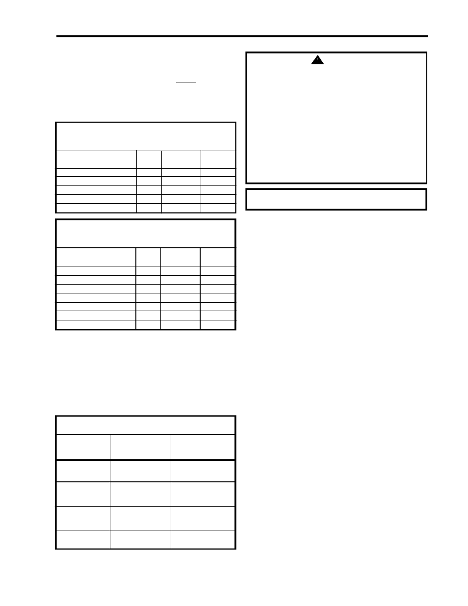
TABLE - 9
2" (5.1 cm) PVC VENT CONNECTOR LENGTHS FROM INSIDE WALL
FOR LOW GROUND CLEARANCE INSTALLATIONS
Terminating
# of Maximum Minimum
Elbows Length Length
(2) 90° Elbows with Vent Terminal
0
35 ft (10.7 m)
2 ft (.6 m)
(2) 90° Elbows with Vent Terminal
1
30 ft (9.2 m)
2 ft (.6 m)
(2) 90° Elbows with Vent Terminal
2
25 ft (7.6 m)
2 ft (.6 m)
(2) 90° Elbows with Vent Terminal
3
20 ft (6.1 m)
3 ft (.9 m)
(2) 90° Elbows with Vent Terminal
4
15 ft (4.6 m)
4 ft (1.2 m)
TABLE - 10
3" (7.6 cm) VENT CONNECTOR LENGTHS FROM INSIDE WALL
FOR LOW GROUND CLEARANCE INSTALLATIONS
Terminating (Reduce 3" to 2") # of Maximum Minimum
(Reduce 7.6 cm to 5.1 cm)
Elbows Length Length
(2) 90° Elbows with (1) 90° Elbow
1
60 ft (18.3 m)
10 ft (3 m)
(2) 90° Elbows with Vent Terminal
0
90 ft (27.5 m)
10 ft (3.1 m)
(2) 90° Elbows with Vent Terminal
1
85 ft (25.9 m)
10 ft (3.1 m)
(2) 90° Elbows with Vent Terminal
2
80 ft (24.4 m)
10 ft (3.1 m)
(2) 90° Elbows with Vent Terminal
3
75 ft (22.9 m)
10 ft (3.1 m)
(2) 90° Elbows with Vent Terminal
4
70 ft (21.4 m)
10 ft (3.1 m)
(2) 90° Elbows with Vent Terminal
5
65 ft (19.8 m)
12 ft (3.7 m)
WARNING
Liquefied petroleum gases/propane gas are heavier than air and will remain
at floor level if there is a leak. Basements, crawl spaces, closets and areas
below ground level will serve as pockets for accumulation of leaking gas.
Before lighting, smell all around the appliance area for gas. Be sure to smell
next to the floor.
WHAT TO DO IF YOU SMELL GAS
• Do not try to light any appliance.
• Do not touch any electrical switch; do not use any telephone
in your building.
• Immediately call your gas supplier from a neighbor’s
telephone. Follow the gas supplier’s instructions.
• If you cannot reach your gas supplier, call the fire department.
DO NOT OPERATE APPLIANCE UNTIL LEAKAGE IS CORRECTED!
IMPORTANT
The flow of combustion and ventilating air must not be obstructed.
TABLE - 11
HIGH ALTITUDE VENT CONNECTOR MODIFICATIONS
Altitude above
Maximum venting
Maximum venting
sea level
length reduction
length reduction
tables 7 & 9
tables 8 & 10
Reduce maximum vent
length by 20 ft (6.1 m)
No reduction in vent
length required
over 2,000 - 5,000ft
(over 610 - 1524 m)
0 - 2,000 ft
(0 - 610 m)
No reduction in vent
length required
over 5,000 - 8,000 ft
(over 1524 - 2439 m)
Use only 3" (7.6 cm)
PVC (Tables 8 & 10)
No reduction in vent
length required
over 8,000 - 10,000 ft
(over 2439 - 2540 m)
Use only 3" (7.6 cm)
PVC (Tables 8 & 10)
Reduce maximum vent
length by 20 ft (6.1 m)
No reduction in vent
length required