Lochinvar RPV-I&S User Manual
Page 3
3
RPV-I&S
76,000 BTU (283.9 L - 22.3 kW/Hr) models. Part II will cover
venting specifications for 40 Gal - 40,000 BTU (151.4 L - 11.7 kW/
Hr) and 48 gal - 40,000 BTU (181.7 L - 11.7 kW/Hr) models. Refer
to the rating plate located on the water heater for correct model
identification.
The National Fuel Gas Code ANSI Z223.1-(Latest Edition), CGA/CAN B149
Installation Code, and local codes have specific requirements for the location
of the vent terminals on vertical walls. The guide lines listed below are from
the National Fuel Gas Code. Consult the local codes, and/or National Fuel Gas
Code ANSI Z223.1-(Latest Edition), or CGA/CAN B149 Installation Code to
determine if there are any additions or changes to the following specifications.
(A) The vent terminal must terminate at least 3 feet (.91 m) above any
forced air inlet duct located within 10 feet (3 m). Exception: This
provision shall not apply to the combustion air intake of a direct vent
appliance.
(B) The vent terminal must terminate at least 4 feet (1.2m) below, 4 feet
(1.2 m) horizontally from, or 1 foot (0.31 m) above any door, window,
gravity air inlet into the building.
(C) The bottom of the vent terminal must be located at least 1 foot
(0.31 m) above ground and above the anticipated snow level.
(D) The vent terminal must not terminate over a public walkway or over an
area where condensate or vapor could create a nuisance or hazard
or could be detrimental to the operation of regulators, relief valve, or
other equipment.
(E) The water heater location must provide easy access for the entire
length of the vent connector.
(F) The vent system must be inspected at least once a year to ensure
against leakage of exhaust products.
Exceptions For Installations in Canada:
(A) The vent terminal must be located at least 1 foot (0.31 m) from any
window or door which can be opened in any building, any non-mechanical
air supply inlet to any building, or the combustion air to any inlet other
appliance.
(B) The vent terminal must be located at least 6 feet (1.8 m) from any
mechanical air supply inlet to the building.
(C) The vent terminal must not terminate above a meter/regulator
assembly within 3 feet (0.91 m) horizontally of the vertical center line
of the regulator and must be at least 6 feet (1.8 m) from any gas
service regulator vent outlet.
(D) The vent terminal must be at least 7 feet (2.1 m) above a paved
sidewalk or a paved driveway located on public property.
(E) The vent terminal must not terminate above a paved sidewalk or a
paved driveway, which is located on private adjacent property.
VENTING SYSTEM CONDENSATION
Condensate formation does not occur in all installations of power vented
heaters, but should be protected against on installations where condensation
can form in the venting system.
Formation of condensation in the venting system of Power Vented water
heaters is dependent upon installation conditions including, but not limited to:
1. Ambient temperature and humidity of installation location;
2. Ambient temperature and humidity of venting space; vent distance and
slope;
3. And product usage.
In order to effectively control condensate from adversely affecting the
mechanical components of the water heater several methods may be employed:
1. For horizontal installations the vent pipe can be installed with a downward
slope (not less than 1/8" nor greater than 1/2” per foot maximum) and
away from the blower motor.
2. In order to prevent condensate from draining back into the blower (vertical
or horizontal runs), a fitting and drain hose is available as a condensate
trap kit (see Table 1 for service part numbers). The all rubber fitting with
drain outlet mounts directly to the blower motor outlet and is secured with
two hose clamps (one to the blower motor outlet and the other to the vent
connector). The plastic tubing is provided to drain any accumulated
condensate away from the water heater and to a suitable drain. The kit
comes complete with instructions for proper installation of the fitting.
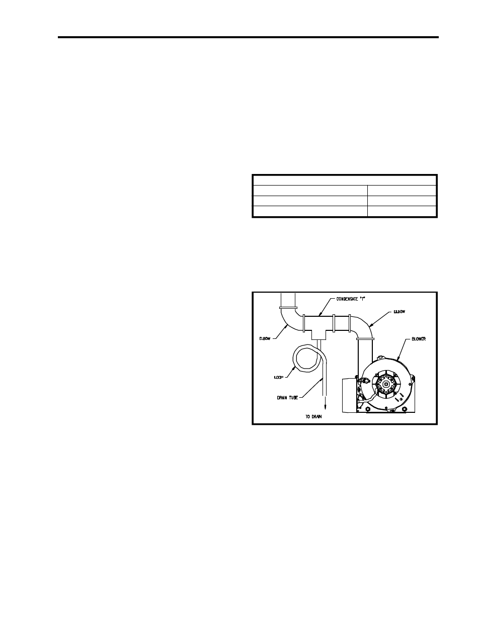
3. In order to prevent condensate from draining back into the blower (vertical
or horizontal runs), a drain tee and condensate trap can be installed in the
horizontal vent as close as practical to the blower vent connection (see
Figure1). The condensate disposal tube should be installed to drain any
accumulated condensate away from the water heater and to a suitable
drain. The drain tee and condensate hose should be available through
your local distributor.
Part I - Venting Specifications for:
48 Gallon, 65,000 BTU input (181.7 L, 19.1 kW/Hr)
65 Gallon, 65,000 BTU input (246.1 L, 19.1 kW/Hr)
75 Gallon, 76,000 BTU input (283.9 L, 22.3 kW/Hr)
This water heater is a power vented appliance and is designed to vent its
products of combustion through 3" (7.6 cm) or 4" (10.2 cm) diameter Schedule
40 (solid or cellular core) PVC pipe to the outdoors. This water heater may be
either vented through the wall or vertically through the roof. Use a 3" (7.6 cm)
to 4" (10.2 cm) reducer to connect to the vent outlet when using 4" (10.2 cm)
PVC. Table 2 lists the maximum vent lengths for this water heater using 3" (7.6
cm) PVC. If possible, locate the water heater so that the venting length and
number of elbows are kept to the minimum distance necessary to reach the
outside. If the installation requires venting lengths that exceed the lengths
listed for 3" (7.6 cm) PVC in Table 2, then use 4" (10.2 cm) PVC for the vent
connector. Table 3 lists the venting distances allowed with 4" (10.2 cm)
Table - 1
Model Service Part
2" (5.1 cm) Blower Outlet (exhaust)
DRV1200
3" (7.6 cm) Blower Outlet (exhaust)
DRV1201
Figure 1