Lennox Hearth Elite Series RDV-CK-LP TO NG User Manual
Page 2
READ ALL THE STEPS BEFORE STARTING THE CONVERSION.
INSTALLER NOTICE: THESE INSTRuCTIONS MuST BE LEFT wITH
THE APPLIANCE.
This kit contains components required to convert this appliance
from using Propane Gas to using Natural Gas as the only fuel.
All of these components must be replaced in order for the unit to
operate safely on Natural Gas.
when installing gas components use pipe joint compound or
Teflon tape on all pipe fittings before installing (ensure propane
resistant compounds are used, do not use pipe joint compounds
on flare fittings).
INSTALLATION INSTRuCTIONS
Step 1. TuRN OFF THE GAS SuPPLY TO THE APPLIANCE.
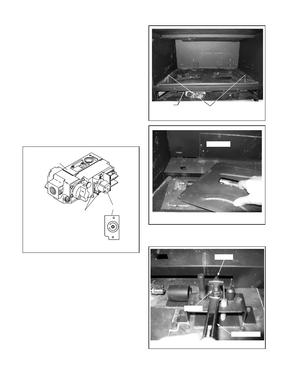
Step 2. Using a phillips screwdriver, remove and discard the two pressure
regulator mounting screws (see Figure 3). Remove the pressure
regulator and rubber gasket. Discard all removed components.
Install the new regulator. Ensure the rubber gasket on the back
of the pressure regulator is properly positioned when installing
the new pressure regulator using the new screws supplied with
this kit. Locate the label provided in the regulator kit. Write in
the required information, then affix it to the valve.
Fill out & affix label from
regulator kit to valve
Step 6. Using a 7/16” open-end wrench, loosen the stem of pilot hood
assembly with a 1/4 turn counterclockwise (see Figures 5 & 6).
Remove These
Screws
Regulator
Gas Valve
(located in control com-
partment below firebox)
Figure 3 - Replace Regulator on Valve
Step 3. Remove the glass door by releasing the two upper spring latches,
and lifting up, out of the lower latches (see Page 18 of the Instal-
lation and Operation Manual). Carefully remove the logs. Exercise
care so as not to break the logs. Set aside in a safe place.
Step 4. Remove log rack by first removing the two 5/32” allen head
screws. Note: Screws secure log rack and front of burner. After
screws are removed you can pull the lock rack straight out mak-
ing sure it’s held high enough to clear over the pilot assembly.
See Figure 4A.
Step 5. Remove burner by shifting it to the right until it releases from
air shutter. Air shutter may need to be shifted to the left before
burner will release. Remove 5/32” air shutter screw before mov-
ing air shutter. See Figures 4A and 4B.
Figure 5
Pilot Hood
Pilot Stem
7/16” End wrench
Figure 4A
Log rack and burner screws
Burner
Air shutter
screw
Burner
Lift Out Burner
Figure 4B
NOTE: DIAGRAMS AND ILLUSTRATIONS ARE NOT TO SCALE.
2