Life Fitness CLST User Manual
Page 9
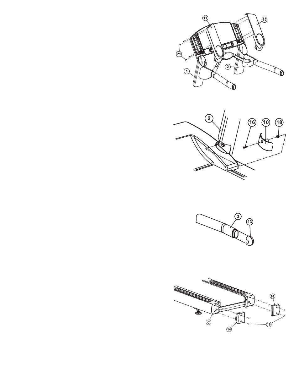
16. Locate the L
EFT
A
CCESSORY
T
RAY
(11). Carefully slide the tray into
the top of the L
EFT
U
PRIGHT
(1) as shown until fully seated.
Secure the accessory tray to the L
EFT
T
OP
M
OUNTING
P
LATE
(H)
using four S
CREWS
(21). Repeat the procedure for the R
IGHT
A
CCESSORY
T
RAY
(12) and R
IGHT
T
OP
M
OUNTING
P
LATE
(J).
17. Tighten all U
PRIGHT
B
OLTS
securely.
18. Replace the M
OTOR
C
OVER
(E) and secure the M
OTOR
C
OVER
to the F
RAME
(C) using the four previously removed S
CREWS
(D). Tighten the S
CREWS
securely. Do not overtighten the
S
CREWS
.
19. Replace the F
RONT
G
RILL
(B) and secure the F
RONT
G
RILL
to the
F
RAME
(C) using the four previously removed S
CREWS
(A).
Tighten the S
CREWS
securely. Do not overtighten the S
CREWS
.
20. Locate one S
CREW
G
ROMMET
(18). Insert the S
CREW
G
ROMMET
into the square hole located above the top inside mounting bolt
of the R
IGHT
U
PRIGHT
(2). Repeat for the remaining S
CREW
G
ROMMET
and L
EFT
U
PRIGHT
(1).
21. Locate one L
OWER
U
PRIGHT
C
OVER
(10). Position the L
OWER
U
PRIGHT
C
OVER
at the bottom notch of the R
IGHT
U
PRIGHT
(2)
making sure the top lip of the U
PRIGHT
C
OVER
is engaged under
the outside notch of the R
IGHT
U
PRIGHT
. Secure the U
PRIGHT
C
OVER
to the R
IGHT
U
PRIGHT
using one S
CREW
(16). Tighten the
S
CREW
securely. Do not overtighten the S
CREW
. Repeat the pro
cedure for the L
EFT
U
PRIGHT
(1) and remaining U
PRIGHT
C
OVER
.
22. Locate the U
PRIGHT
P
LUGS
(25). Insert one U
PRIGHT
P
LUG
into
each of the two access holes located on the lower outside of the
L
EFT
and R
IGHT
U
PRIGHTS
(1 & 2).
23. Locate and press the H
ANDLEBAR
C
APS
(13) over the ends of the
H
ANDLEBARS
(3). Be sure the H
ANDLEBAR
C
APS
are fully seated.
24. Using two S
CREWS
(16) each, attach the two R
EAR
F
RAME
E
ND
C
APS
(14) to the F
RAME
(C) as shown. Tighten the S
CREWS
securely. Do not overtighten the S
CREWS
.
25. The treadmill striding belt must be “walked-in” for five
minutes after assembly is complete.
Plug the treadmill into an appropriate outlet. Turn the treadmill on
at the on/off switch. Select QUICK START from the console.
Increase the speed to 3 mph (4.8 km/h). Start walking in the front
left corner of the walking surface and drift to the back, move to
the center of the deck and walk towards the front, and finally
walking to the right corner and drifting to the back. Continue
pattern for five minutes.
26. Refer to the specific treadmill’s Operation Manual for power
requirements, proper line cord routing, and other critical product
information before connecting the treadmill to a power source
7