Life Fitness CLST User Manual
Page 8
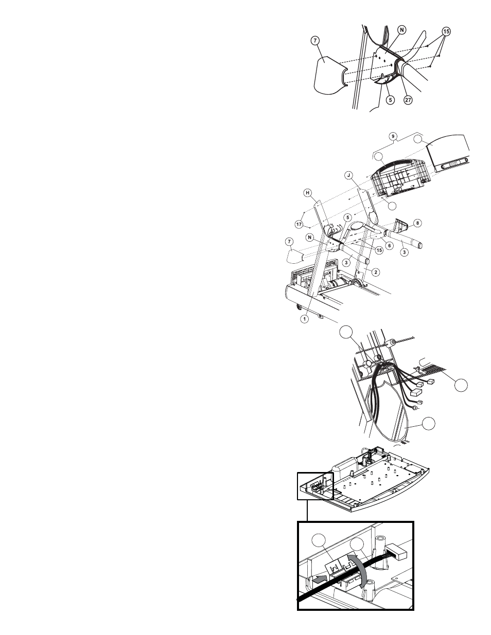
6
12. Slide the L
EFT
I
NSIDE
H
ANDLEBAR
S
HROUD
(5) near the L
EFT
U
PRIGHT
H
ANDLEBAR
B
RACKET
(N).
Position the H
ANDLEBAR
G
ROMMET
(27) at the end of the L
EFT
I
NSIDE
H
ANDLEBAR
S
HROUD
. Install the H
ANDLEBAR
G
ROMMET
onto
the inside edge of the L
EFT
I
NSIDE
H
ANDLEBAR
S
HROUD
as shown.
Locate and position the L
EFT
O
UTSIDE
H
ANDLEBAR
S
HROUD
(7) to
match the L
EFT
I
NSIDE
H
ANDLEBAR
S
HROUD
.
Install the remaining portion of the H
ANDLEBAR
G
ROMMET
onto the
L
EFT
O
UTSIDE
H
ANDLEBAR
S
HROUD
as it is positioned to match the
L
EFT
I
NSIDE
H
ANDLEBAR
S
HROUD
.
Secure the S
HROUDS
together using three S
CREWS
(15). Tighten
the S
CREWS
securely. Do not overtighten the S
CREWS
. Repeat the
procedure for the R
IGHT
I
NSIDE
and O
UTSIDE
H
ANDLEBAR
S
HROUDS
(6 & 8).
13. Locate the D
ISPLAY
C
ONSOLE
(9). Remove the eight S
CREWS
(P)
from the back of the D
ISPLAY
C
ONSOLE
and separate the front of
the D
ISPLAY
C
ONSOLE
from the rear. Position the R
EAR
C
ONSOLE
(Q) over the L
EFT
and R
IGHT
T
OP
M
OUNTING
P
LATES
(H & J) as
shown. From the bottom of the L
EFT
and R
IGHT
T
OP
M
OUNTING
P
LATES
, secure the R
EAR
C
ONSOLE
using four S
CREWS
(17).
Tighten the S
CREWS
securely. Do not overtighten the S
CREWS
.
14. Position and rest the F
RONT
C
ONSOLE
(R) face down across the
H
ANDLEBARS
(3). Connect all C
ONNECTORS
leading from the L
EFT
(if equipped) and R
IGHT
U
PRIGHTS
(1 & 2) to the corresponding
C
ONNECTORS
located on the F
RONT
C
ONSOLE
. Feed any excess
W
IRE
H
ARNESS
into the U
PRIGHTS
. Carefully route all W
IRE
H
ARNESSES
through the W
IRE
H
ARNESS
G
UIDES
(S) located at the
lower left of the R
EAR
C
ONSOLE
(Q).
Note: Consoles for the European Union countries are
equipped with a F
ERRITE
(T)
. Open the F
ERRITE
(T). Route the
M
AIN
W
IRE
H
ARNESS
(G) through the F
ERRITE
. Close the F
ERRITE
.
15. Tilt the F
RONT
C
ONSOLE
(R) upright and in position over the R
EAR
C
ONSOLE
(Q). Secure the F
RONT
C
ONSOLE
to the R
EAR
using the
previously removed eight S
CREWS
(P). Tighten the S
CREWS
securely. Do not overtighten the S
CREWS
.
Note: Be careful not to pinch any cables when assembling
the F
RONT
C
ONSOLE
(R) to the R
EAR
C
ONSOLE
(Q).
S
Q
1
Q
R
P
T
G