Operation, Warning, Caution – Lincoln Electric LN -15 WIRE FEEDER IM823-A User Manual
Page 22
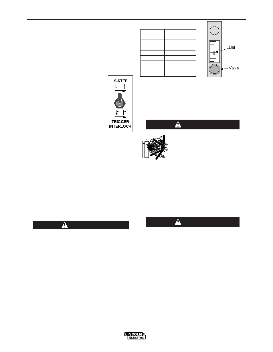
SCFH
Liter/Min.
10
4.7
20
9.4
30
14.2
40
18.9
50
23.6
60
28.3
70
33.1
80
37.8
SPINDLE BRAKE
Adjust the spindle brake tension to allow the spool to
spin freely, yet have enough resistance for little or no
overrun when wire feeding is stopped.
SHIELDING GAS CONNECTION
CYLINDER may explode if
damaged.
• Keep cylinder upright and
chained to support.
• Keep cylinder away from areas where it may be
damaged.
• Never lift welder with cylinder attached.
• Never allow welding electrode to touch cylinder.
• Keep cylinder away from welding or other live
electrical circuits.
-----------------------------------------------------------------------
• B U I L D U P O F S H I E L D I N G G A S M A Y H A R M
HEALTH OR KILL.
• Shut off shielding gas supply when not in use.
• See American National Standard Z-49.1, "Safety
i n W e l d i n g a n d C u t t i n g ” P u b l i s h e d b y t h e
American Welding Society.
-----------------------------------------------------------------
Customer must provide a cylinder of shielding gas,
a pressure regulator, a flow control valve and a hose
from the flow valve to the gas inlet fitting of the
LN™-15.
Connect a supply hose from the gas cylinder flow
valve outlet to the 5/8-18 female inert gas fitting on the
back of the LN™-15.
WARNING
WARNING
B-7
OPERATION
B-7
LN™-15 ACROSS THE ARC MODEL & (CE)
Hold with toggle switch in the DOWN position to acti-
vate Gas Purge and let the shielding gas flow. The
gas solenoid valve will energize but neither the power
source output nor the drive motor will be turned on.
The Gas Purge switch is useful for setting the proper
flow rate of shielding gas. Flow meters should always
be adjusted while the shielding gas is flowing.
2 STEP - TRIGGER INTERLOCK SWITCH
The 2 Step - Trigger Interlock switch
changes the function of the gun trigger.
2 Step trigger operation turns welding on
and off in direct response to the trigger.
Trigger Interlock operation allows weld-
i n g t o c o n t i n u e w h e n t h e t r i g g e r i s
released for comfort on long welds.
Place the toggle switch in the UP posi-
tion for 2 Step operation or in the DOWN
position for Trigger Interlock operation.
2 Step Trigger
2 Step trigger operation is the most common. When
the gun trigger is pulled, the welding power source
energizes the electrode output and the wire feeder
feeds wire for welding. The power source and wire
feeder continue welding until the trigger is released.
Trigger Interlock
Trigger Interlock operation provides for operator com-
fort when making long welds. When the gun trigger is
first pulled, the welding power source energizes the
output and the wire feeder feeds wire for welding.
The gun trigger is then released while the weld is
made. To stop welding, the gun trigger is pulled again,
and when it is released the welding power source out-
put turns off and the wire feeder stops feeding wire.
If the arc goes out while welding with trigger inter-
lock operation, the electrode output from the
welding power source remains energized and the
wire feeder will continue to feed wire until the gun
trigger is again pulled and then released.
-----------------------------------------------------------------
FLOW METER
The flowmeter shows the flow rate of shielding gas
and has a valve to adjust the flow. The flow meter is
calibrated for CO2, Ar, and CO2/Ar blends. The mid-
dle of the ball indicates the flow rate of shielding gas.
Adjust the flow rate by turning the valve at the bottom
of the meter. Most weld procedures require 25-40 scfh
(11.8 - 18.9 lpm) for sufficient shielding gas coverage.
Gun angle, nozzle diameter, joint configuration and
wind conditions may effect the amount of shielding
gas required.
CAUTION