Table 19, Table 20, Figure 15 – Liebert 1500 User Manual
Page 22: Figure 16, 16 specifications, 2) 400 a
16 Specifications
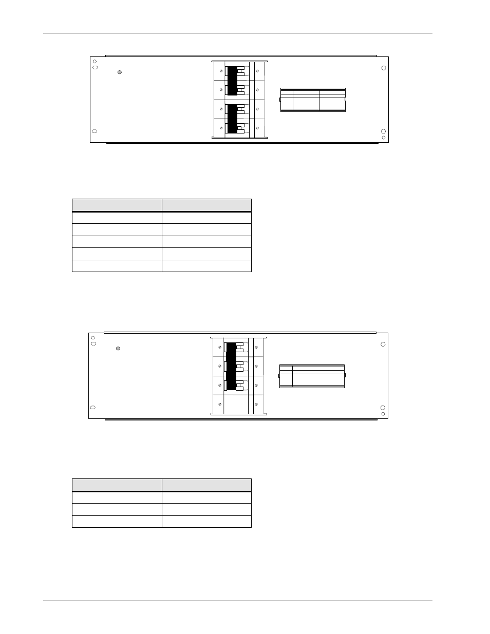
Figure 15 Front view of the (2) 400 A circuit breaker panel
The DC output connections can accommodate two 750 MCM cables back to back for each circuit
breaker. The required lugs must be for two 1/2” holes at 1-3/4” c-c.
Refer to Table 21 for the maximum panel capacity.
The panel accepts up to:
• two breakers (400 A) mid trip with or without the metering shunt option
• one breaker (400 A) mid trip with the relay trip option (takes a 3 pole space)
Figure 16 Front view of the (1) 600-700 A circuit breaker panel
The DC output connections can accommodate four 750 MCM cables back to back. The lugs must
be for two 1/2” bolts at 1-3/4” c-c.
Refer to Table 21 for the available circuit breakers and the maximum panel capacity.
Table 19
Circuit breaker kits available for the (2) 400 A circuit breaker panel
Nominal current
CPC
400 A (no shunt)
P0748316
400 A (with shunt)
P0748317
2 x 400 A (no shunt)
P0748318
2 x 400 A (with shunt)
P0748319
400 A (with relay trip)
P0748320
Table 20
Circuit breaker kits available for the (1) 600-700 A circuit breaker panel
Nominal current
CPC
600 A (no shunt)
P0875700
600 A (e/w shunt)
P0875701
600 A (e/w relay trip)
P0875702
900A MAX. PANEL CAPACITY
1
2
CIRCUIT BREAKER PANEL
NT6C12EF
FA
REL ( )
SER NO ( )
UNIT
AMPS
LOAD
400
400
1
2
(2) 400 A
900A MAX. PANEL CAPACITY
1
2
CIRCUIT BREAKER PANEL
NT6C12EG
FA
REL ( )
SER NO ( )
UNIT
AMPS
LOAD
600
1
(1) 600-700 A