Linksys BEPSR11 User Manual
Page 10
EtherFast
®
Cable/DSL Routers
Full/Col
Green. The Full/Col LED also serves two purposes. If this
LED remains lit, a LAN port connection is being successful-
ly maintained. If the LED flickers, the connection is experi-
encing collisions. Infrequent collisions are normal.
If this LED flickers too often, there may be a problem with
your connection. See “Appendix A: Troubleshooting” if you
encounter this problem.
10/100
Orange. The 10/100 LED lights up when a successful
100 Mbps connection is made through the corresponding
port.
If a connection is running at 10 Mbps, the 10/100 LED will
not light up.
The WAN Indicators
Link
Green. The Link LED lights up when a successful connec-
tion is made between the Router and your broadband device
or network.
Act
Green. The Act LED flickers when the Router is sending or
receiving data over the WAN port.
Diag
Red. The Diag LED lights up when the Router goes through
its self-diagnostic mode. It will turn off upon successful
completion of the diagnosis.
If this LED stays on for an abnormally long period of time,
see “Appendix A: Troubleshooting.”
Proceed to “Chapter 5: Connect the Router.”
13
Instant Broadband
™
Series
12
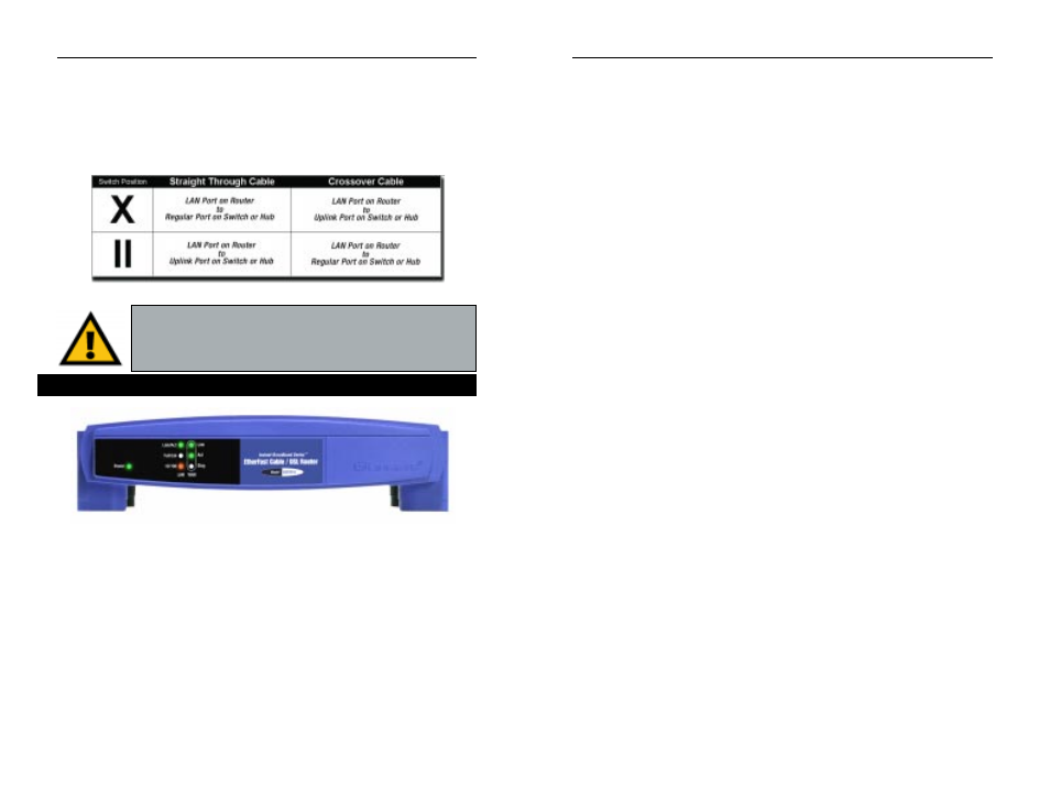
The Crossover Switch
When “uplinking,” or connecting two pieces of network hardware together,
such as a hub and a switch, a general rule of thumb is to plug one end of a
network cable into a straight-through port, and the other end into a crossover
port (uplink port). Standard ports are straight-through ports, and uplink ports
are crossover ports.
T h e
1
-
Port
Power
Green. The Power LED lights up green when the Router is
powered on.
Link/Act
Green. The Link/Act LED serves two purposes. If the LED
is continuously lit, the Router is successfully connected to a
device through the LAN port. If the LED is flickering, the
Router is actively sending or receiving data through the LAN
port.
Important: The chart in Figure 3-2 is for reference purposes
only. Every network is different. If you do not make a connec-
tion to a hub or switch by using the settings above, change the
position of the Crossover Switch.
The 1-Port Router’s Front Panel LEDs
Figure 3-2
Figure 3-3