Interrupt configuration – Lynx EPM-4 User Manual
Page 46
Interrupt Configuration
Reference – 38
EPM-4 Reference Manual
Interrupt Configuration
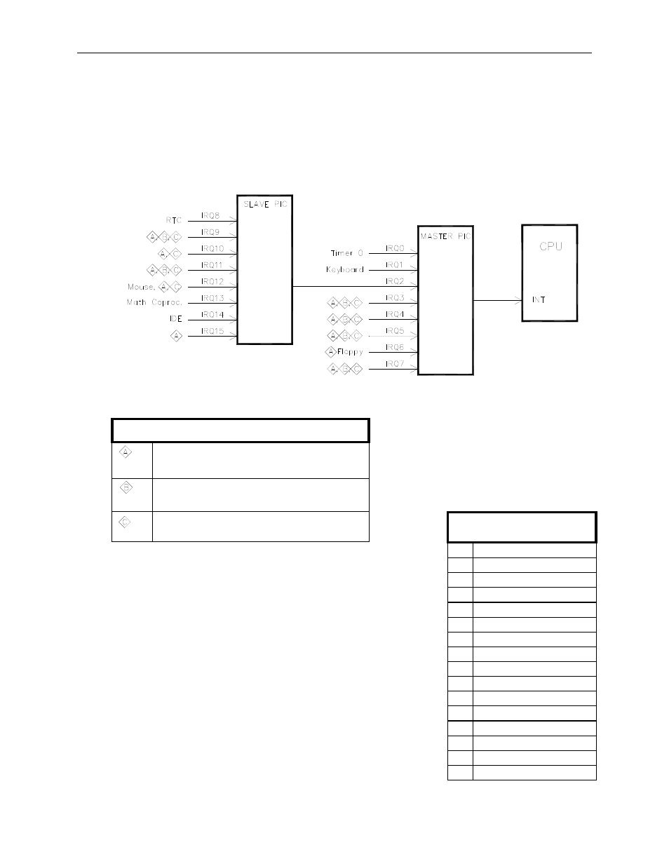
Default interrupt settings on the Lynx have been selected to maintain PC/AT compatibility. They
can be re-routed to satisfy customer constraints. Use the custom configuration screen in BIOS
setup to configure IRQ’s on the Lynx Not all devices can use all IRQ’s. Refer to Figure 8 for a
description of allowable IRQ assignments for each device.
Figure 8. Interrupt Circuit Diagram
Components Group:
COM1, COM2, GP Timers, Watchdog,
PCI Interrupts.
COM3, COM4, LPT1
Available on PC/104 (ISA) bus
Default IRQ assignments:
0
Timer
0
1
Keyboard
2
Slave PIC cascade
3
COM2
4
COM1
5
Unused
6
Floppy
drive
7
Unused
8
Real-Time
Clock
9
Unused
10
Unused
11 PCI Interrupt A,B,C,D
12
PS/2
Mouse
13
Math
Co-processor
14
IDE
controller
15
Unused