Interface mode, 2 interface mode -9, Table 23 - interface mode options -9 – Lantronix Device Server UDS 10 User Manual
Page 95: Table 24 - common interface mode settings -9, Interface mode (see, Table 23 - interface mode options
UDP
UDS-10 User Guide
8-9
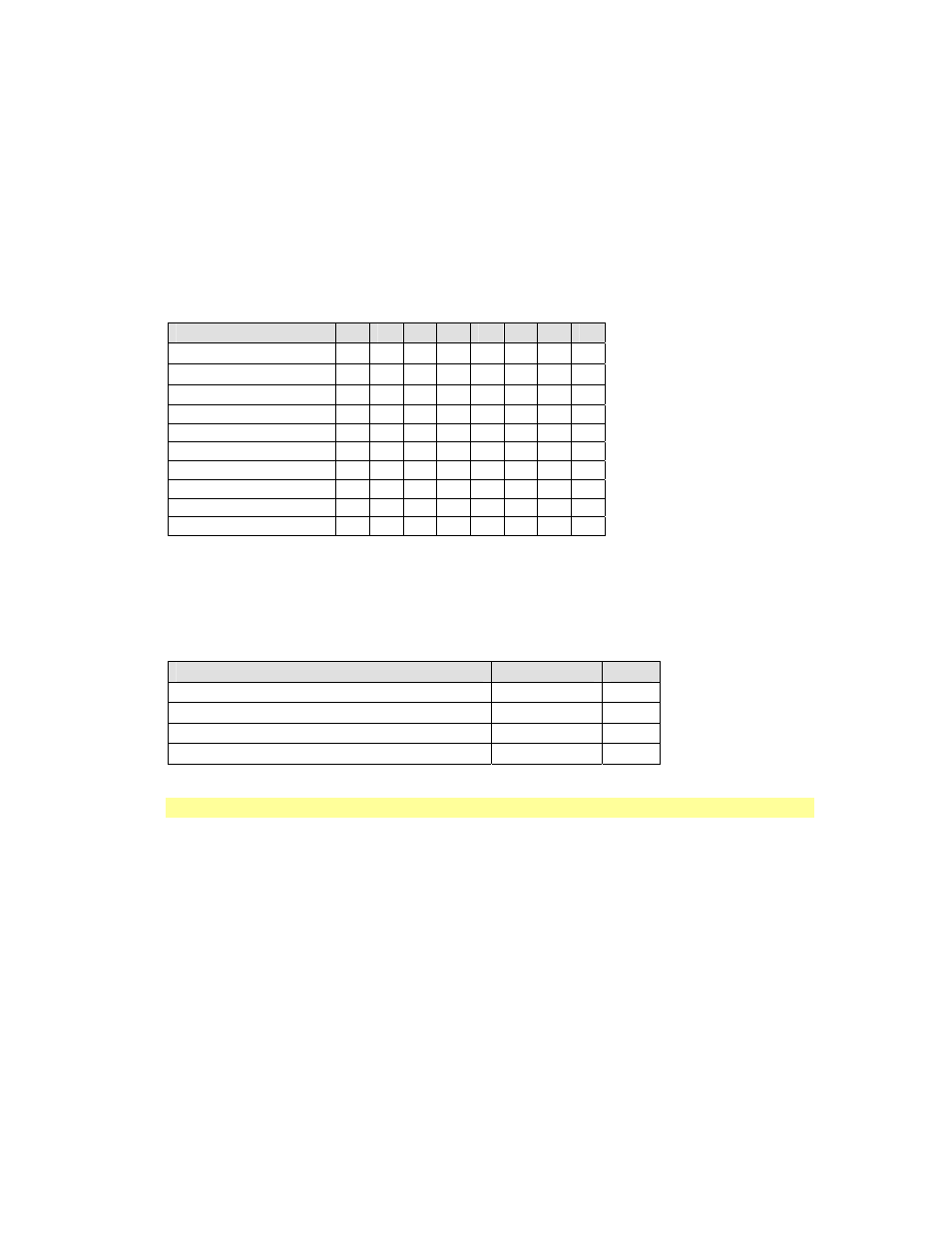
8.3.2 Interface Mode
The Interface (I/F) Mode is a bit-coded byte entered in hexadecimal notation. Use the
following table to select Interface Mode settings:
Table 23 - Interface Mode Options
I/F Mode Option
7
6
5
4
3
2
1
0
RS-232C
(1)
0
0
RS-422/485
(1)
0
1
RS-485 2-wire
(1)
1
1
7
Bit
1 0
8
Bit
1 1
No Parity
0
0
Even
Parity
1 1
Odd
Parity
0 1
1
Stop
bit
0 1
2
Stop
bits
1 1
(1) The UDS-10 requires you to choose the correct setting in the IF mode.
The following table demonstrates how to build some common Interface Mode settings:
Table 24 - Common Interface Mode Settings
Option
Binary
Hex
RS-232C, 8-bit, No Parity, 1 stop bit
(1)
0100 1100
4C
RS-232C, 7-bit, Even Parity, 1 stop bit
(1)
0111 1000
78
RS-485 2-Wire, 8-bit, No Parity, 1 stop bit
(1)
0100 1111
4F
RS-422, 8-bit, Odd Parity, 2 stop bits
(1)
1101 1101
DD
(1) The UDS-10 requires you to choose the correct setting in the IF mode.
Note: See Table 35 - Binary to Hexadecimal Conversion Table.