Honeywell electronic gas valve, Sit millivolt gas valve – Lennox Hearth EBVSTNM-B User Manual
Page 9
9
NOTE: DIAGRAMS & ILLUSTRATIONS ARE NOT TO SCALE.
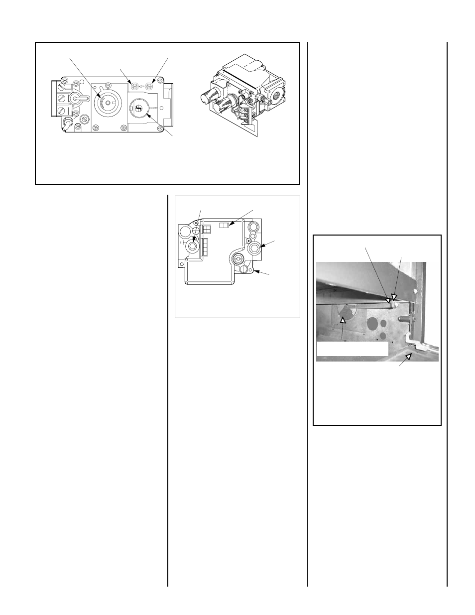
Figure 3
Honeywell Electronic
Gas Valve
Figure 2
Note: The piezo igniter is located on the modesty panel - refer to Figure 1.
Variable Flame Height Adjustment
( Millivolt Appliances only)
All Millivolt appliances are equipped with a
variable gas control valve. Flame height for
these models may be adjusted through a range
between fixed low and high settings, alternately,
while the appliance is in operation.
Adjust the flame height as desired after lighting
the appliance by rotating the variable adjustment
control knob located on the front of the valve
(refer to Figure 2). (An extension is provided to
this knob so that the adjustment may be made
at the modesty panel).
HI
LO W
TPTH
TP
TH
PILO
T
PIL
OT
ON
it
OFF
Variable Flame Height Adjustment
Manifold Pressure Port
Inlet Pressure Port
Main Gas
Control Knob
IN
OUT
SIT Millivolt Gas Valve
ON/OFF Switch
Electronic
Gas Control
Valve
Inlet
Pressure
Port
Manifold Pressure Port
OFF
IN
P
S
I
ON
CONTROL
IG
N
IT
ER
Outside Combustion Air Controls
Many appliances are equipped, when installed,
with an outside (make-up air) vent system
that is designed to provide the appliance with
outside make-up air for combustion when
in operation. The outside air control lever
for the outside air system is standard on all
appliances but should not be operated if the
complete system is not installed. Refer to
Figure 4. When the complete outside air vent
system is installed, the installer will remove
the securing screw from the combustion air
control lever located on the right side of the
fireplace opening.
If the securing screw has not been removed
and you have reason to believe that you have
a complete outside air system, contact your
distributor to have your appliance inspected for
the presence of the complete system. DO NOT
assume that you have this system in place.
Outside Air Control Lever
and Securing Screw Location
(EBVST and EBVPF Units Shown)
Figure 4
Outside Air Control Lever with Stop Behind
Securing Screw
Outside Air Shutter in the
Closed Position
Control Compartment Access Panel