Assembly instructions step #2 – Keys Fitness ST-2600 User Manual
Page 7
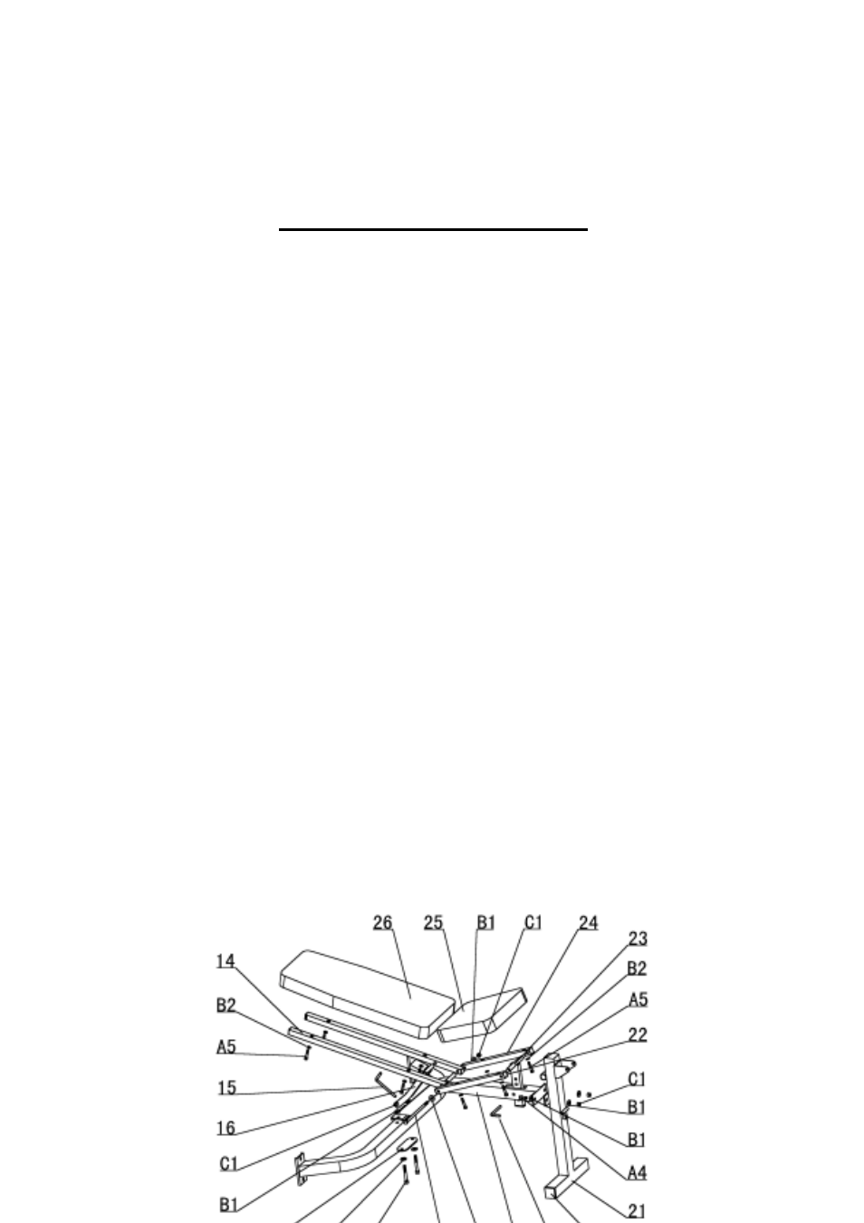
ASSEMBLY INSTRUCTIONS
STEP #2
B)
ng two
C)
mainframe so that the welded tube is at the
D)
f one
side hole of the other backrest tube, through the hole
E)
to an upright, military position by
F)
d can be
.
A)
Attach the front base (#21) to the mainframe (#18) with two bolt M10X25(#A4), four
washers 10 (#B1) and two nylon nuts M10 (#C1)
Attach the mainframe/front base assembly to the center of the cross bar (#10) usi
bolts M10x75 (#A3), four washers 10 (#B1) and two nylon nuts M10 (#C1). Install the
oval reinforcement plate on the underside of the cross bar during this assembly.
Attach the backrest tubes (#14) and seat tubes (#24) to the mainframe. Push the backrest
fixed bar (#16) into the hole of the backrest tubes as illustrated. Set the seat adjustment
bracket (#23) down into the hole on top of the
top and resting across the mainframe. Push the seat adjustment bracket through the hole
near the front of one seat tube as illustrated.
Push a bolt M8x195 (#A1) with a washer 10 (#B1) through the hole nearest the end o
of the shorter seat tubes. Push the bolt all the way through the seat tube, and then into
the single side hole of one of the longer backrest tubes. Push the bolt through the
backrest tube and then through the small welded tube across the top of the mainframe.
Continue to push the bolt through the
nearest the end of the other seat tube, then out the other side. Secure with one washer 10
(#B1) and one nylon nut M10 (#C1).
Attach the backrest pad (#26) to the backrest tubes using four bolts M8x40 (#A5) and four
washers 10 (#B2). The backrest pad can be put in
pushing the long lock pin (#15) through the hole in the mainframe and resting the bottom
of the backrest tubes against the back of the pin
Attach the seat pad (#25) with the wider end to the rear, to the top of the seat tubes using
four bolts M8X40 (#A5) and four washers 10 (#B2). The position of the seat pa
adjusted by raising or lowering the front edge. Push the short lock pin (#19) through one
of the holes in the seat adjustment bracket and let it rest on top of the mainframe