Tk-2160, Adjustment – Kenwood TK-2160 User Manual
Page 26
TK-2160
26
■ Frequency and signalling
The set has been adjusted for the frequencies shown in
the following table. When required. re-adjust them following
the adjustment procedure to obtain the frequencies you want
in actual operation.
Frequency (MHz) K, M type
Channel No.
RX Frequency
TX Frequency
1
155.05000
155.10000
2
136.05000
136.10000
3
173.95000
173.90000
4
155.00000
155.00000
5
155.20000
155.20000
6
155.40000
155.40000
7~16
Signalling
Signalling No.
RX
TX
1
None
None
2
None
100Hz Square Wave
3
QT 67.0Hz
QT 67.0Hz
4
QT 151.4Hz
QT 151.4Hz
5
QT 210.7Hz
QT 210.7Hz
6
QT 254.1Hz
QT 254.1Hz
7
DQT D023N
DQT D023N
8
DQT D754I
DQT D754I
9
DTMF 159D
DTMF 159D
10
None
DTMF tone 9
2 Tone:
2 Tone:
11
A:321.7Hz
A:321.7Hz
B:928.1Hz
B:928.1Hz
12
None
Single Tone:1000Hz
13
None
MSK
14
MSK Code
MSK Code
Adjustment Frequency
K,M
TEST CH
RX
TX
Center
155.050MHz
155.000MHz
Low
136.050MHz
136.000MHz
High
173.950MHz
174.000MHz
Low’
145.550MHz
145.500MHz
High’
164.550MHz
164.500MHz
155.000MHz
155.000MHz
155.200MHz
155.200MHz
155.400MHz
155.400MHz
•
Preparations for tuning the transceiver
Before attempting to tune the transceiver, connect the unit
to a suitable power supply.
Whenever the transmitter is tuned, the unit must be
connected to a suitable dummy load (i.e. power meter).
The speaker output connector must be terminated with a
8W dummy load and connected to an AC voltmeter and an
audio distortion meter or a SINAD measurement meter at all
times during tuning.
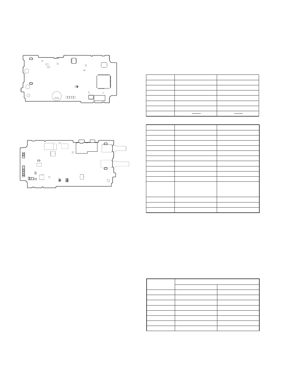
ADJUSTMENT
Adjustment points TX-RX unit (X57-672)
Component side view
Foil Side View
VR1 : Frequency adjustment
RSSI : Band-pass wave form test point
TC1 : Transmit lock voltage adjustment
TC2 : Receive lock voltage adjustment
CV : Lock voltage adjustment terminal.
SP MUTE
RESET
VR1
DET
BATT+
ANT
TXD
SP–
SP+
PTTI
(RXD)
PTTO
GND
AUX
PTT
S-1
S-2
RSSI
CV
X57-672 A/2
Component side
TC1
TC2
ALT
CV
A4
A3
A4
A1
MIC O
RA O
A6
A4
GND
SB
RA I
MIC I
5C
DEO
TXAFI
PTT
LSDFO
ALT2
BPF
ANT
X57-672 A/2
Foil side
Fig. 1 Adjustment points