Navigation – Kicker SX SERIES SX650.1 User Manual
Page 8
15
SX .1 Series Amplifiers
Opera
tion
Navigation
Your KICKER SX series amplifier uses the latest in Digital DSP
control and provides you with valuable operational informa-
tion about your amplifier, real-time diagnostics and a full
multi-level menu-driven operating system to access and
adjust your amplifier.
The menu system is designed in layers. There is a starting
point and you keep drilling down until you get to the menu
item you want to view or change. This menu tree is an
example of how the SX menu structure is set up.
NOTE: Not all the menus and menu items are shown below.
DEFAULT
SCREEN
SYSTEM
GAIN
EQ
LO-PASS
HI-PASS
CURRENT
HISTORY
∝
...
∝
...
∝
*
MAIN MENU
SYSTEM MENU
SICK BAY MENU
VOLT NOW
VOLT MIN
VOLT MAX
TEMP NOW
TEMP MAX
∝
...
RUN TIME
SICK BAY
As you can see there can be an infinite number of menu
levels and each one of these menu levels can have an infinite
number of its own items.
Navigating this simple menu
structure is very easy using the 5-way
keypad.
You use the
UP
and
DOWN
keys to scroll through the
available menu items, and the
ENT
key is used to select that
menu item. The
ESC
key backs you up one menu level from
where you are, and the
HOME
key can return you all the
way to MAIN MENU by pressing and holding it for 1.5 seconds.
For example let’s begin at the DEFAULT SCREEN; our goal is
to get to the HISTORY menu. Pressing the
ENT
key would get
us to MAIN MENU. Now use the
UP
and
DOWN
keys to scroll to SYSTEM, and
then press the
ENT
key. Now you are
in the SYSTEM MENU. Using the
UP
and
DOWN
keys again you scroll to SICK
BAY and press the
ENT
key. You are
now in the SICK
BAY MENU. Use the
UP
and
DOWN
keys again to scroll to HISTORY and then
press the
ENT
key. That’s it! You are
there.
This is how you view information
and change settings in your KICKER SX amplifier.
HOME
ENT
ESC
HOME
ENT
ESC
HOME
ENT
ESC
14
SX .1 Series Amplifiers
I
NST
ALLA
TION
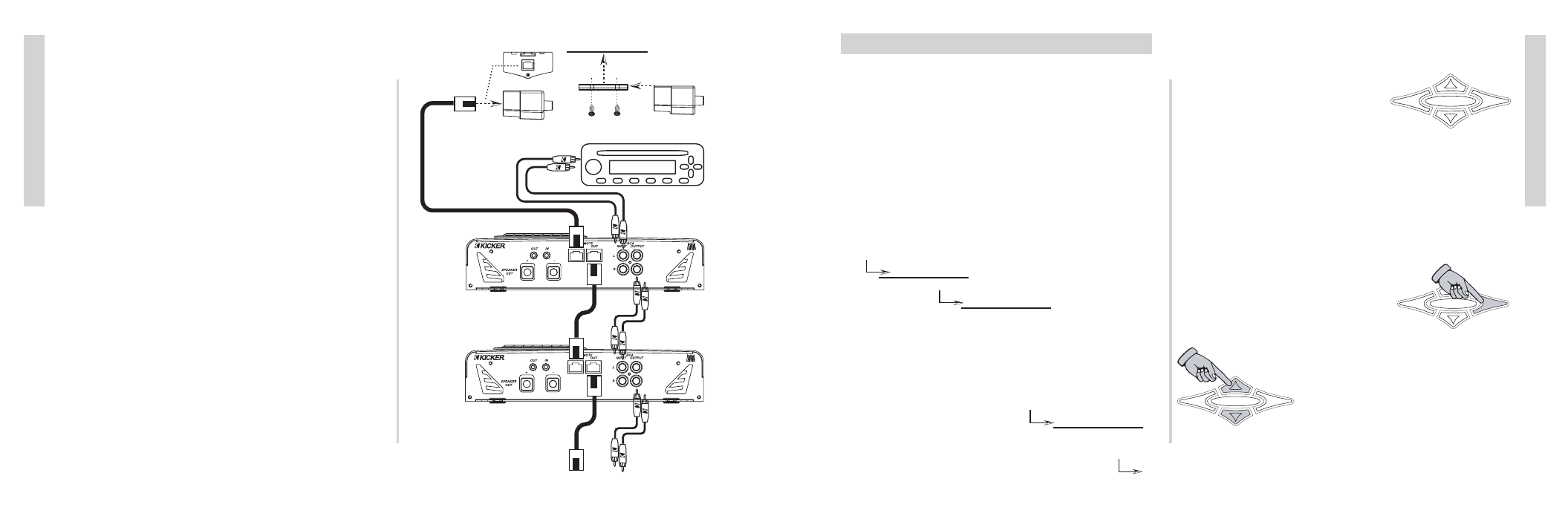
USING THE REMOTE BASS LEVEL CONTROL & BLAST
You can use the Remote Bass Level Control to control the
output of your amplifier from the front of the car.
Mount the controller by simply screwing the metal bracket
to the chosen location and then slide the housing onto the
bracket until it snaps into place.
Route the cable from the controller to the BLAST input jack
on the amplifier chassis. That’s it.
If you wish to control more than one amplifier with your
remote, you will simply need to use a RJ45 cable (not supplied
but available at any Radio Shack, computer store or electronics
center) to connect the BLAST output jack of the first amp to
the BLAST input jack of the next amplifier.
SOURCE UNIT
To Next Amplifier
AMP STRAPPING
AMP STRAPPING
BACK VIEW
SIDE VIEW
Mounting Surface
SUPPLIED
CABLE
OPTIONAL
RJ45 CABLE
OPTIONAL
RJ45 CABLE