Kawasaki 840330 User Manual
Page 7
A
AT
TT
TA
AC
CH
HIIN
NG
G W
WIIR
RE
E B
BR
RU
US
SH
HE
ES
S
Wire cup brushes, not included, can be screwed directly on the spindle. No flanges are
necessary.
E
ED
DG
GE
E G
GR
RIIN
ND
DIIN
NG
G
D
Do
o n
no
ott u
usse
e e
ed
dg
ge
e g
grriin
nd
diin
ng
g w
wh
he
ee
ellss ffo
orr ccu
utt--o
offff w
wo
orrkk,, d
de
ee
ep
p
g
grriin
nd
diin
ng
g o
orr ssu
ub
bjje
ecctt tth
he
em
m tto
o a
an
nyy ssiid
de
e p
prre
essssu
urre
e a
ass tth
hiiss m
ma
ayy lle
ea
ad
d tto
o b
brre
ea
akka
ag
ge
e
a
an
nd
d p
po
ossssiib
blle
e p
pe
errsso
on
na
all iin
njju
urryy.. These wheels should be used for shallow cutting
and notching (less than 1/2" in depth). Keep the open side of the guard away
from the operator at all times.
Edge grinding should only be done with wheels specifically designed for this purpose.
R
RE
EM
MO
OV
VIIN
NG
G G
GU
UA
AR
RD
D F
FO
OR
R S
SA
AN
ND
DIIN
NG
G O
OR
R U
US
SIIN
NG
G F
FL
LA
AT
T W
WIIR
RE
E B
BR
RU
US
SH
HE
ES
S
• Set the Angle Grinder on a flat surface with the spindle facing up.
• Remove the inner and outer flanges, unscrew spring washer and remove
the guard.
• Store these parts carefully.
• Replace the guard after the job is finished.
A
AT
TT
TA
AC
CH
HIIN
NG
G S
SA
AN
ND
DIIN
NG
G D
DIIS
SC
C
• To remove the guard, see instructions given in the “Removing Guard for
Sanding or Using Flat Wire Brushes” Section above.
• Set the inner flange and outer flange on the spindle.
• Push in the spindle lock button. Turn the spindle until it locks into place.
• Once the spindle is locked, tighten the sanding disc by hand.
O
OP
PE
ER
RA
AT
TIIN
NG
G T
TH
HE
E A
AN
NG
GL
LE
E G
GR
RIIN
ND
DE
ER
R
A
Allw
wa
ayyss u
un
np
pllu
ug
g tth
he
e tto
oo
oll b
be
effo
orre
e a
atttte
em
mp
pttiin
ng
g tto
o cch
ha
an
ng
ge
e tth
he
e
g
gu
ua
arrd
d o
orr a
acccce
esssso
orriie
ess..
For best tool control, material removal and minimal
loading, keep the angle between the disc and the work surface at approximate-
ly 30° when grinding and 10°-15° when sanding.
WARNING
12
A
AT
TT
TA
AC
CH
HIIN
NG
G W
WH
HE
EE
EL
LS
S W
WIIT
TH
H D
DE
EP
PR
RE
ES
SS
SE
ED
D C
CE
EN
NT
TE
ER
RS
S
A
Allw
wa
ayyss cch
he
ecckk tth
he
e tto
oo
oll w
wa
arrn
niin
ng
g lla
ab
be
ell ffo
orr tth
he
e rre
ecco
om
mm
me
en
nd
d--
e
ed
d ssp
pe
ee
ed
d rra
attiin
ng
g o
on
n a
acccce
esssso
orriie
ess.. Never run a wheel or brush over the rated
speed. Accessories exceeding the recommended speed may fly apart and cause
serious personal injury.
H
Hu
ub
bb
be
ed
d w
wh
he
ee
ellss d
do
o n
no
ott rre
eq
qu
uiirre
e m
mo
ou
un
nttiin
ng
g fflla
an
ng
ge
ess..
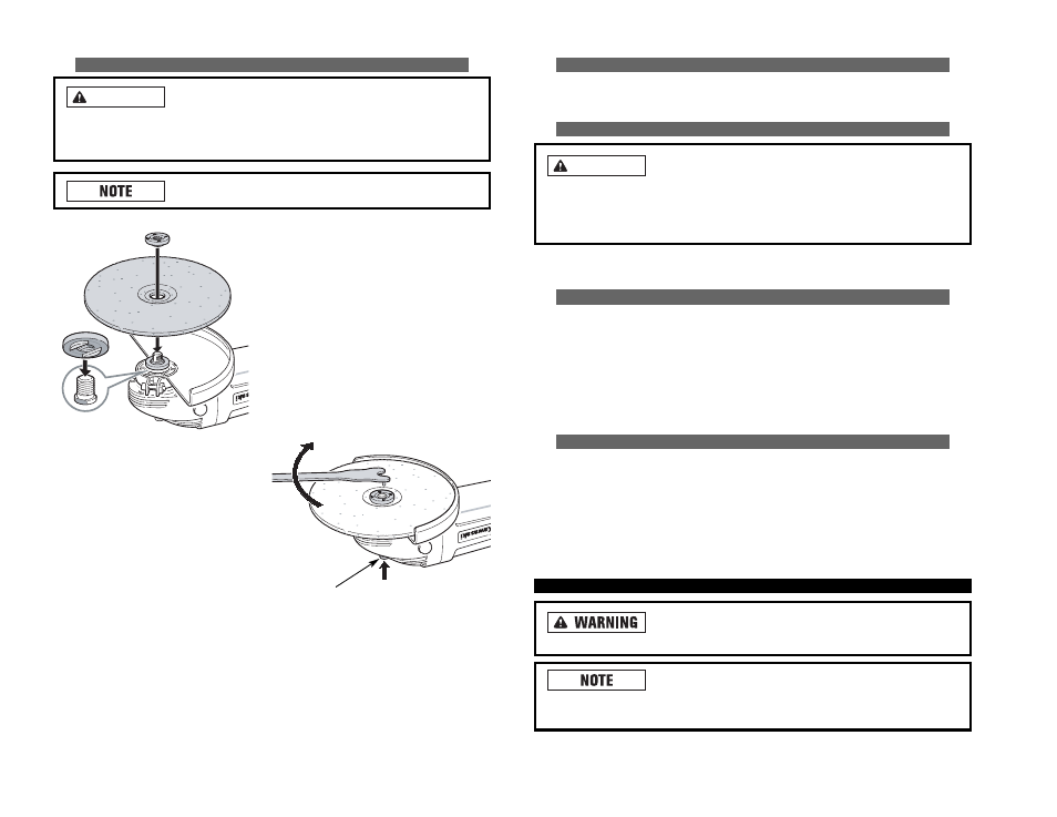
• When working with thick grinding
wheels, fit the threaded outer flange
with the raised area facing away
from the wheel.
• Push in the spindle lock button.
Turn the outer flange until it locks
into place.
• Once the spindle is locked, insert
the enclosed wrench into the holes
of the outer flange to tighten the
outer flange properly.
WARNING
11
SPINDLE
LOCK
BUTTON
• Check to make sure that the guard is fit-
ted properly. Put the inner flange on
the spindle.
• Put the grinding wheel on the spindle
and the inner flange.
• When working with thin grinding wheels,
fit the threaded outer flange with the
raised area facing toward the wheel.