Kawasaki 840330 User Manual
Page 6
A
AT
TT
TA
AC
CH
HIIN
NG
G A
AU
UX
XIIL
LIIA
AR
RY
Y H
HA
AN
ND
DL
LE
E
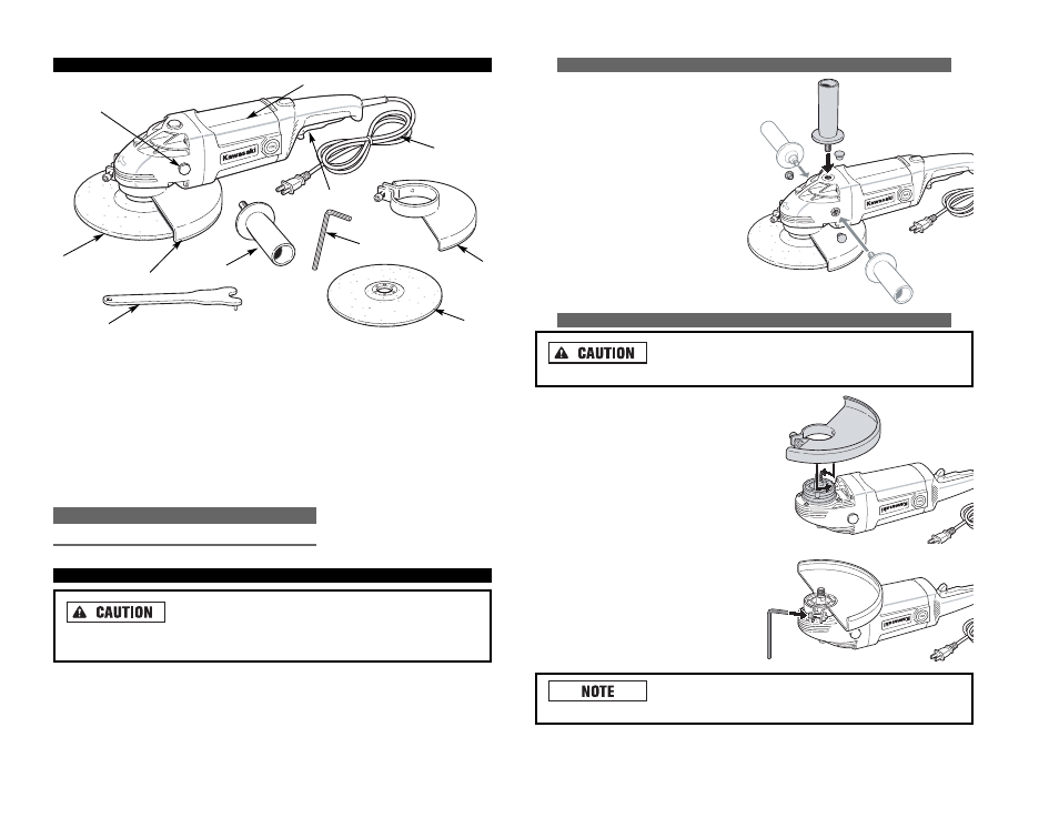
This tool comes with an auxiliary
handle which can be attached to the
left, right or top side of the Angle
Grinder, depending on the prefer-
ence of the operator. This handle is
necessary to maintain complete
control of the tool and should be
used at all times. Make sure this
handle is always fastened securely.
A
AT
TT
TA
AC
CH
HIIN
NG
G W
WH
HE
EE
EL
L G
GU
UA
AR
RD
D
N
Ne
evve
err b
brru
ussh
h o
orr g
grriin
nd
d w
wiitth
ho
ou
utt tth
he
e g
gu
ua
arrd
d iin
n p
plla
acce
e.. Brushes
are considered to be grinding wheels and must also be used with guards.
• Always unplug the tool before attempt-
ing to change the guard or accessories.
• Set the Angle Grinder on a flat surface
with the spindle facing up.
• Place the spring washer of the guard
over the spindle.
• Tighten the screw of the spring washer.
• Make sure that the guard is secure-
ly tightened in place.
Wheel size MUST match guard size. A 7" wheel may not be
used in a 9" guard.
F
FU
UN
NC
CT
TIIO
ON
NA
AL
L D
DE
ES
SC
CR
RIIP
PT
TIIO
ON
N
C
CO
ON
NT
TR
RO
OL
LS
S A
AN
ND
D C
CO
OM
MP
PO
ON
NE
EN
NT
TS
S::
1. ON/OFF Switch with Locking Tab
2. Tool Body
3. Protective Guard
4. 9" Grinding Wheel
5. Spindle Lock Button
6. Power Cord
C
CO
OM
MP
PO
ON
NE
EN
NT
T
M
MO
OD
DE
EL
L N
NU
UM
MB
BE
ER
R
Pin Spanner
690157
A
AS
SS
SE
EM
MB
BL
LY
Y
M
Ma
akke
e ssu
urre
e yyo
ou
u h
ha
avve
e ffu
ullll cco
on
nttrro
oll o
off tth
he
e tto
oo
oll w
wh
he
en
n g
grriin
nd
diin
ng
g
iin
ntto
o a
a cco
orrn
ne
err a
ass a
a ssh
ha
arrp
p,, ssu
ud
dd
de
en
n m
mo
ovve
em
me
en
ntt m
ma
ayy o
occccu
urr w
wh
he
en
n tth
he
e w
wh
he
ee
ell
cco
on
ntta
accttss a
a sse
ecco
on
nd
da
arryy ssu
urrffa
acce
e..
9
A
AC
CC
CE
ES
SS
SO
OR
RIIE
ES
S::
7. Side Handle
8. Pin Spanner
9. Hex Wrench
10. 7" Grinding Wheel
5
4
8
3
6
10
9
3
7
1
2