Optional components – Sanyo MPR-1411R User Manual
Page 35
- 72 -
34
OPTIONAL COMPONENTS
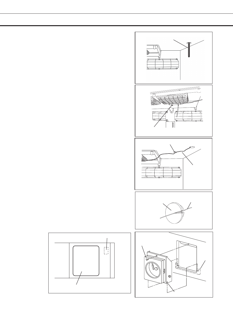
3. Remove the black rubber caps (inside and outside)
on the access port located at the top corner of the unit
and take the insulation out of the access port.
4. Pass the recorder sensor into the chamber through
the access port. (Fig. 3)
5. An attached binder (two pcs) is used for the fan
cover of the top of the chamber as the Fig. 4, and a
temperature sensor is fixed.
4. Route the capillary on the top of the chamber and fix
it with the provided clip and screw. (Fig. 5)
5. Make a cut on the rubber caps so that the capillary
can pass the caps and place them back on the access
port (inside and outside). (Fig. 6)
9. Bind the lead wire on the right upper side of the unit
with the provided band.
10. Remove the connector cap located on the right side
and then connect the recorder power. (Fig. 7)
11. Attach the recorder on the front cover with a screw.
(Fig. 8)
Fig. 3
Temperature
recorder sensor
Fig. 7
Connector for recorder power
Space for temperature recorder
Binder
Fig. 4
Fig. 5
Clip
Capillary
Capillary
Rubber cap
Fig. 6
Fig. 8
Screw
Shaft
Channel