Data connections – Sentry Industries PT40 User Manual
Page 58
Data Connections
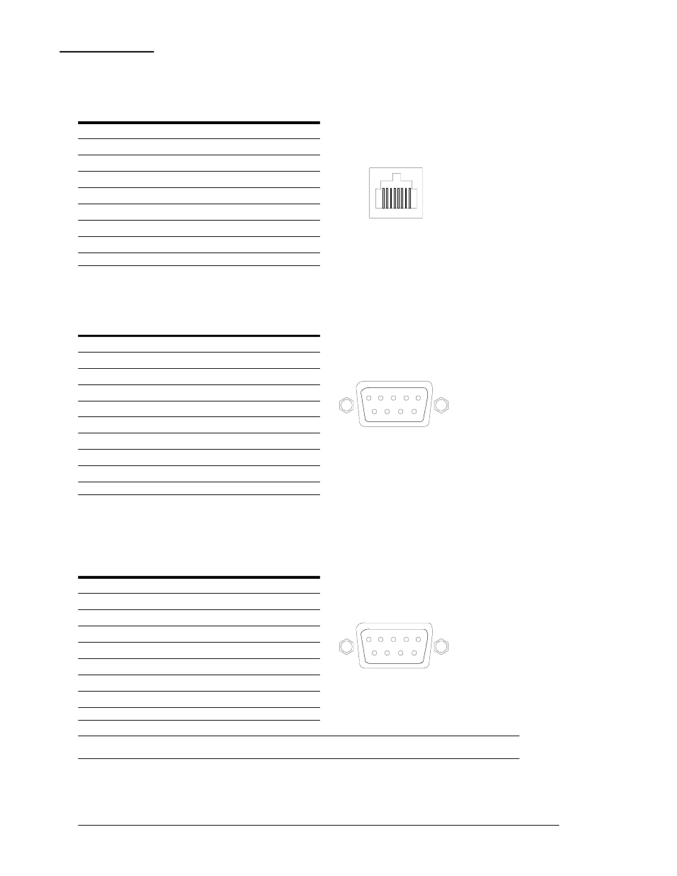
RS-232 port
Sentrys are equipped standard with an RJ45 DTE RS-232c serial port. This connector may be used for
direct local access or from other serial devices such as a terminal server. An RJ45 crossover cable is
provided for connection to an RJ45 DCE serial port.
Pin
DTE Signal Name
Input/Output
1
Request to Send
RTS
Output
2
Data Terminal Ready DTR
Output
6
7 54321
8
3
Transmit Data
TD
Output
4 Signal
Ground
5
Signal Ground
6
Receive Data
RD
Input
7
Data Set Ready
DSR
Input
8
Clear to Send
CTS
Input
RJ45 to DB9F serial port adapter
Additionally, an RJ45 to DB9F serial port adapter is provided for use in conjunction with the RJ45
crossover cable to connect to a PC DB9M DCE serial port. The adapter pinouts below reflect use of the
adapter with the provided RJ45 crossover cable.
Pin
DCE Signal Name
Input/Output
1
2 Receive
Data
RD Output
1
2
3
4
5
6
7
8
9
3 Transmit
Data TD
Input
4
Data Terminal Ready DTR
Input
5
Signal Ground
6
Data Set Ready
DSR
Output
7
Request to Send
RTS
Input
8
Clear to Send
CTS
Output
8
Clear to Send
CTS
Output
Modem Port
Sentrys without an integrated modem are equipped with a DB9-male RS-232C DTE Modem serial port.
This connector is typically used to connect to an external modem, but may also be used to connect to
any RS-232C device. A 9-pin female to 25-pin male cable is included for connecting the Sentry RPM to
an external modem.
Pin
DTE Signal Name
Input/Output
1
Data Carrier Detect DCD
Input
2 Receive
Data
RD
Input
1
2
3
4
5
6
7
8
9
3 Transmit
Data TD Output
4
Data Terminal Ready DTR
Output
5 Signal
Ground
6
Data Set Ready
DSR
Input
7
Request to Send
RTS
Output
8
Clear to Send
CTS
Input
Note: To connect to a PC serial port, a null-modem adapter and a female-to-female gender changer are required in addition
to the included cable.
54
• Appendices
Sentry Commander - PT40
Technical Specifications
Installation and Operations Manual