6 description and functioning, 1 circuit diagram, 2 description of the main functions – Studer Innotec XTH 3000-12 User Manual
Page 18: 1 inverter, 2 automatic load detection, Description and functioning, Circuit diagram, Description of the main functions, Au x2 au x1, 17 a
Steca
Xtender
Installation and Operating Instructions 723.932 Xtender V0.511
Seite 18
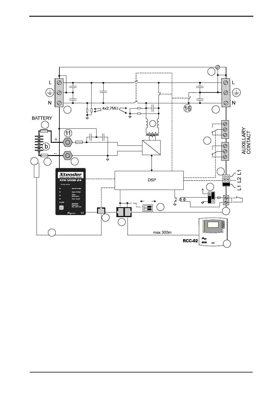
6 Description and functioning
The Xtender is a sine wave inverter with a battery charger. It has been developed for use as a
standalone installation to supply AC voltage (not connected to the grid) or as a continuous supply.
6.1 Circuit diagram
RJ45
AC
I
N
Temp.
AC O
U
T
RJ11
CAN bus
ON
Charge
AC out
AC in
1x
1x
1x
2x
1x
Battery low
1x
2x
3x
4x
Swiss Made
10nF
10nF
2,2nF
100nF
8p
8p
Bus termination
6p
T
O
Remote
On/Off
DC
AC
Au
x2
Au
x1
2,2nF
2,2nF
2,2nF
K1
K2
K3
K4
10
9
14
13
12
2
4
7
6
3
17
a
f
BT
S-
0
1
e
f
t
6.2 Description of the main functions
6.2.1 I
NVERTER
The Xtender is equipped with a high-performance inverter which supplies a perfect and very
precise sine wave. Any unit designed for the 230 V/50 Hz public grid may connect to it without
any problem, up to the rated power out of your Xtender. The inverter is protected against
overloads and short-circuits.
Thanks to the largely over-dimensioned performance level, loads of up to three times greater
than the Xtender’s rated output can be faultlessly supplied for short periods of use, thus allowing
motors to be started up without any problem.
When the Xtender is operating the LED “ON” (43) is glowing.
When the Xtender is in inverter mode, the LED “AC out” (46) is glowing. If it flashes, the inverter
is in “load search” mode (see following chapter “Automatic load detection”).
6.2.2 A
UTOMATIC LOAD DETECTION
In order to save battery energy, the Xtender inverter stops and automatically goes into load
search when the detected load is lower than the sensitivity set by the configuration {1187}. It
automatically goes back into operation when a power consumer greater than this value demands
it. The indicator (46) flashes if the inverter is in “load search” mode, which also indicates that the
AC voltage is present at the output in an intermittent form.
In standby mode the system will thus consume minimal power from the battery (see table of