7 time code system – Sony Ericsson PDW-530P User Manual
Page 38
C
h
apt
er 2
L
oc
at
ions
and
F
un
c
tion
s
of
P
ar
ts
and
Con
tr
ols
38
2-7 Time Code System
2-7 Time Code System
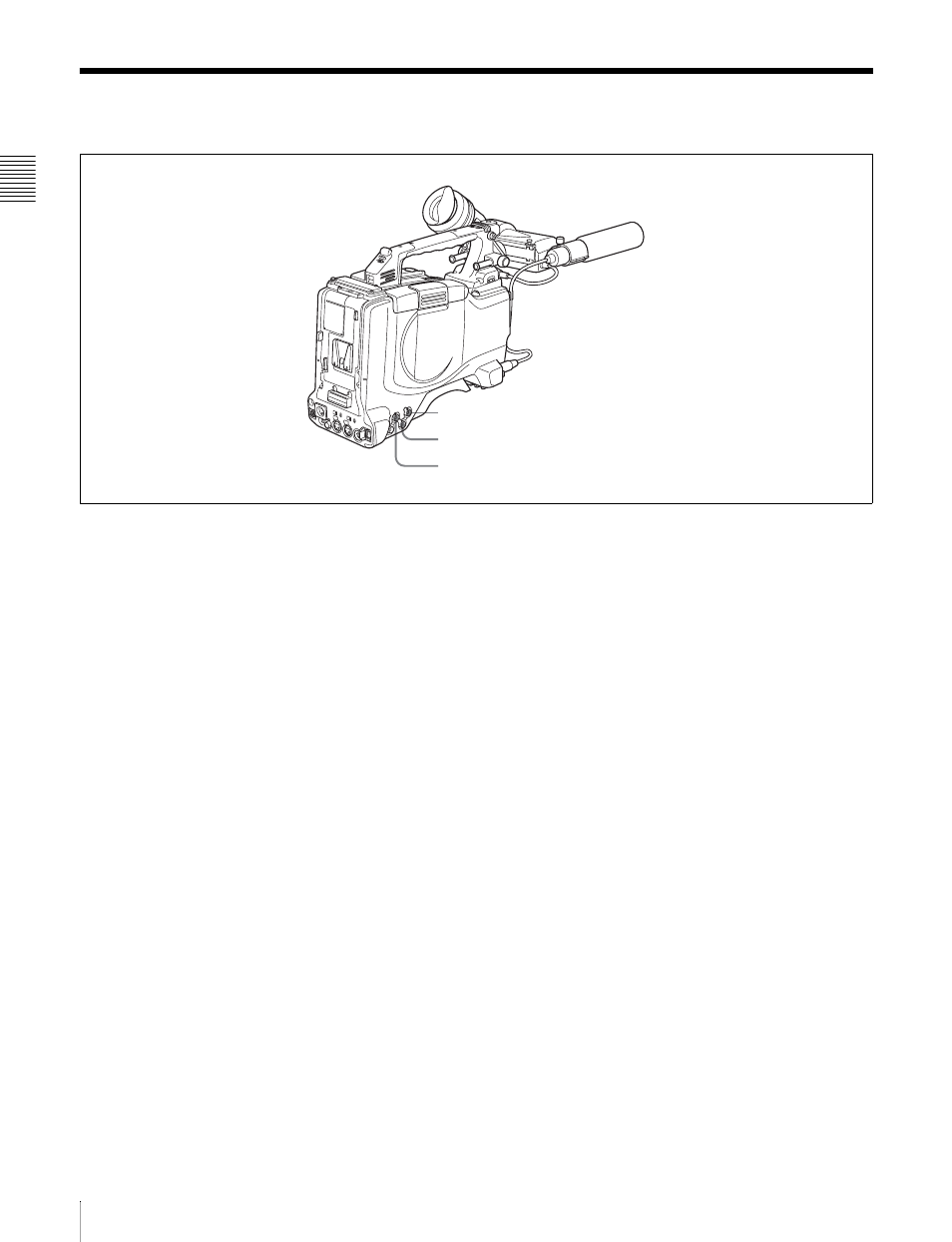
Time code functions (1)
a TC IN (time code input) connector (BNC type)
To synchronize the time code with an external time code,
input the reference time code to this connector.
b TC OUT (time code output) connector (BNC type)
To synchronize the time code of an external VTR with that
of the camcorder, connect this connector to the time code
input connector for time code locking of the external VTR.
c GENLOCK IN connector (BNC type)
• This connector inputs a reference signal when the
camera is to be genlocked or when the time code is to be
synchronized with external equipment. Use the
MAINTENANCE menu to adjust the genlock H-phase
(phase of horizontal sync signal) and the sub-carrier
phase.
For details, refer to the Maintenance Manual.
• This connector also inputs a return video signal. You can
display the image of the return video signal in the
viewfinder screen while holding the RET button down
with “RETURN VIDEO” set to “ON” on the
GENLOCK page of the OPERATION menu.
• This connector also inputs an external analog composite
video signal.
When the CBK-SC01 extension board (not supplied) is
installed, you can record the external analog composite
video signal input to this connector.
For details, see 3-4 “Recording Video Signals from
External Equipment” on page 53.
3
GENLOCK IN connector
1
TC IN connector
2
TC OUT connector