Operation, Specifications, Furnished accessories – Shure SM86 User Manual
Page 2: Optional accessories, Replacement parts
2
OPERATION
Power
The SM86 requires phantom power. This may be supplied to the
microphone from an external power supply (such as the Shure
model PS1A) or directly from preamplifiers, mixers, or consoles
with built-in phantom power. Suitable sources should provide 11 to
52 Vdc phantom voltage.
Impedance
A load impedance of at least 600 Ohms is recommended. The
load may be as low as 150 Ohms, but a reduction in output level and
output clipping level will result.
SPECIFICATIONS
Transducer Type
Condenser (electret bias)
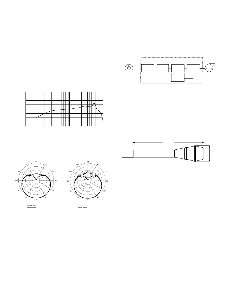
Frequency Response
50 to 18,000 Hz (see Figure 2)
20
20000
1000
10000
50 100
9
8
7
6
5
4
3
29
8
7
6
5
4
3
2
+10
0
–10
Hz
dB
9
TYPICAL FREQUENCY RESPONSE
FIGURE 2
Polar Pattern
Cardioid (see Figure 3)
2500 Hz
6400 Hz
10000 Hz
250 Hz
500 Hz
1000 Hz
TYPICAL POLAR PATTERN
FIGURE 3
Output Impedance
150 Ohms at 1 kHz
Recommended minimum load impedance: 600 Ohms
Sensitivity (at 1,000 Hz)
Open Circuit Voltage
–50 dBV/Pa (3.15 mV)
. . . . . . . . . . . . . . . .
(1 Pa = 94 dB SPL)
Output Clipping Level
1000 Ohm Load at 1,000 Hz
+3 dBV (1.41 V)
. . . . . . . . . . . . . .
Maximum SPL (at 1,000 Hz)
1000
Ω
load (1% THD)
147 dB
. . . . . . . . . . . . . . . . . . . . . . . . . . .
Self-Noise
23 dB typical, A-weighted
Dynamic Range (1000
Ω)
124 dB (maximum SPL to A-weighted noise level)
Signal-to-Noise Ratio
71 dB at 94 dB SPL (IEC 651)*
*S/N ratio is difference between 94 dB SPL and equivalent SPL of self–
noise A-weighted.
Polarity
Positive pressure on diaphragm produces positive voltage on pin
2 relative to pin 3 of the output connector. See Figure 4.
BLACK
REVERSE
VOLTAGE
PROTECTOR
CAPACITOR
(ELECTRET
CONDENSER)
CARTRIDGE
GREEN
RFI FILTER
1
2
3
FET IM-
PEDANCE CON-
VERTER
LF RESPONSE
FILTER
DISCRETE
CLASS A
AMPLIFIER
SM86 BLOCK DIAGRAM
FIGURE 4
Power
Phantom Supply Requirement
11 to 52 Vdc, positive
. . . . . . . .
at both pins 2 and 3
Current Drain
5.2 mA
. . . . . . . . . . . . . . . . . . . . . . . . . . . . . . . . . .
Connector
Three–pin (XLR) professional audio
Case
Dark gray enamel-painted steel with matte-finished silver
colored steel grille
Dimensions
See Figure 5
24 mm
(.95 in.)
49 mm
(1.92 in.)
183 mm
(7.2 in.)
OVERALL DIMENSIONS
FIGURE 5
Net Weight
Net: 278 grams (9.8 oz)
Environmental Conditions
Operating: –18
°
to 60
°
C (0
°
to 135
°
F) (relative humidity <90%)
Storage: –29
°
to 74
°
C (–20
°
to 165
°
F) (relative humidity <80%)
CERTIFICATION
Eligible to bear CE Marking. Conforms to European EMC
Directive 89/336/EEC. Meets applicable tests and performance
criteria in European Standard EN55103 (1996) parts 1 and 2, for
residential (E1) and light industrial (E2) environments.
FURNISHED ACCESSORIES
Break Resistant Microphone Clip
A25D
. . . . . . . . . . . . . . . .
Microphone Bag
26A13
. . . . . . . . . . . . . . . . . . . . . . . . . . . . . .
5/8” to 3/8” Thread Adapter
31A1856
. . . . . . . . . . . . . . . . .
OPTIONAL ACCESSORIES
Phantom Power Supply
PS1A
. . . . . . . . . . . . . . . . . . . . . . . .
Shock Stopper
Isolation Mount
A55M, A55HM
. . . . . . . . .
Popper Stopper
Windscreen
A85WS
. . . . . . . . . . . . . . . .
7.6 m (25 ft.) Cable
C25F
. . . . . . . . . . . . . . . . . . . . . . . . . . . .
REPLACEMENT PARTS
Screen and Grille Assembly
RPM226
. . . . . . . . . . . . . . . . . .
Cartridge and Shock Mount
RPM112
. . . . . . . . . . . . . . . . . . .
Replacement Amplifier Assembly
RPM410
. . . . . . . . . . . . .