Gas supply piping, Electrical wiring – Smith Cast Iron Boilers GS110W User Manual
Page 18
GS110 DIRECT VENT BOILER INSTALLATION AND OPERATION INSTRUCTIONS
Page 18
GAS SUPPLY PIPING
The GS110 hot water boiler comes from the factory
ready to be piped to the gas supply. The gas supply can
be piped from the left or right side of the boiler.
If for any reason the boiler is not for the type of gas
available at the installation site, call the nearest Smith
Cast Iron Boiler distributor to resolve the problem.
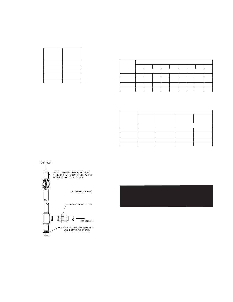
Figure 18 depicts the proper way to connect the boiler
to the gas supply piping. The manual shut-off valve
MUST be installed in the supply piping. It should be
approximately 5 feet above the floor. Provide a sediment
trap/drip leg at the bottom of the vertical section of the
gas supply pipe. A ground joint union should be installed
between the boiler gas controls and the supply piping.
Each of these items is needed to ensure long life and
ease of servicing. Always use a pipe sealant that is
suitable for use with LP gas.
Figure 18 - Gas Supply Piping
CAUTION: Always use a wrench on the gas valve
body when making gas connections to it. Never
over-tighten the piping entering the gas valve body
or the gas valve will be damaged!
Table 8 should be used to ensure that the gas supply
piping is sized properly. If more than one appliance is
supplied by the same supply pipe, the piping must be
sized based on the maximum possible demand. Do not
neglect the pressure drop due to pipe fittings. Table 9
should be used in conjunction with Table 8 to ensure
that the gas supply piping is sized properly.
Safe lighting and other performance criteria were met
with the gas manifold and control assembly provided on
the boiler when the boiler underwent tests specified in
ANSI Z21.13. All gas connections MUST be leak tested
before putting the boiler into operation.
Table 8 - Gas Pipe Capacity
Table 9 - Equivalent Pipe Length Chart
Whenever the gas supply piping is pressure tested the
boiler gas controls must be protected. If the test pres-
sure is equal to, or less than 1/2 psig (3.5 kPa) isolate
the boiler by closing it's manual shut off valve, see
Figure 18. If the test pressure is greater than 1/2 psig
(3.5 kPa), disconnect the boiler and it's individual shut-
off valve from the gas supply piping.
WARNING: Never use an open flame to test for
gas leaks. Always use an approved leak
detection method. Failure to comply with this
WARNING could result in an explosion!
ELECTRICAL WIRING
CAUTION: Label all wires prior to disconnection
when servicing controls. Wiring errors can cause
improper and dangerous operation!
ATTENTION: Au moment de l'entretien des
commandes, étiquetez tous les fils avant de les
débrancher. Des erreurs de câblage peuvent
entraîner un fonctionnement inadéquat et
dangereux. S'assurer que l'appareil fonctionne
adéquatement une fois l'entretirn terminé.
The electrical connections to this boiler/water heater
must be made in accordance with all applicable local
codes and the latest revision of the National Electrical
Code, ANSI /NFPA-70. Installation should also conform
with CSA C22.1 Canadian Electrical Code Part I if
GS110
Section
Size
3
4
5
6
7
Connection
Tapping
1/2"
1/2"
1/2"
3/4"
3/4"
Pipe length in feet
10
20
30
40
50
60
80
100
150
Gas pipe Capacity (ft
3
/hr)
278 190 152
130
115
105
90
79
64
520 350 285
245
215
195
170
150
120
1050 730 590
500
440
400
350
305
250
1600 1100 890
760
670
610
530
460
380
Nominal
Iron Pipe
Size, (in)
3
/
4
″
1
″
1
1
/
4
″
1
1
/
2
″
Type of pipe fitting
90
° Elbow
Tee
Gas Valve
Gas Cock
(branch flow)
(full port)
Equivalent length of pipe fitting in feet
2.6
5.2
0.6
1.5
3.5
6.9
0.8
1.9
4.0
8.0
0.9
2.3
5.2
10.3
1.2
3.0
Nominal
Iron Pipe
Size, (in)
3
/
4
″
1
″
1
1
/
4
″
1
1
/
2
″
Note: Maximum pipe capacity in ft
3
/hr is based on a 0.60 specific
gravity gas at a pressure of 0.5 psig and a 0.3" WC pressure drop.