Machine head, Control elements, Active 2 1 input gain drive 3 – Sound Performance Lab 9737 User Manual
Page 8
8
Machine Head
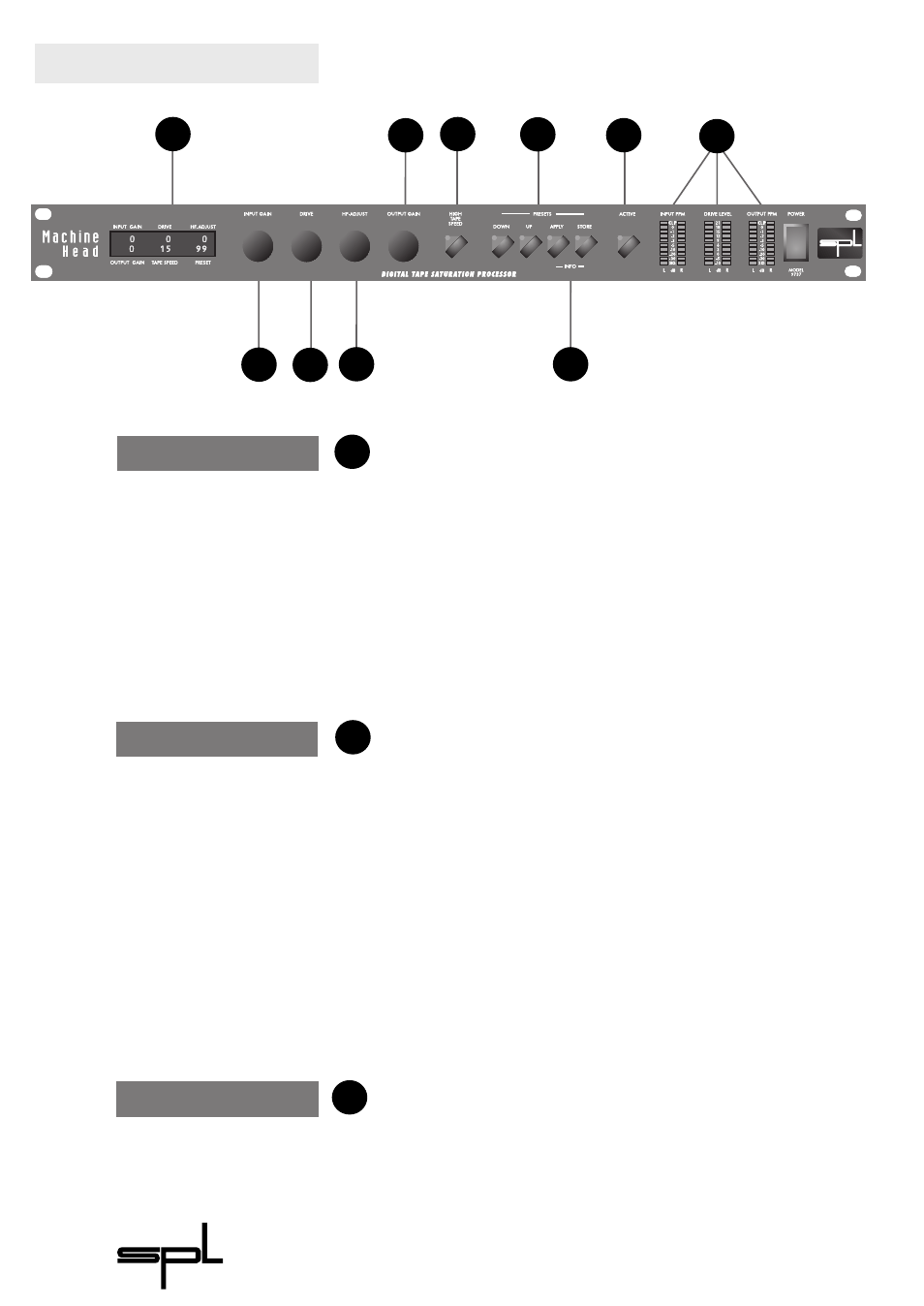
Relay hard-bypass for
AES/EBU input and output
Setting the recording level of
the ‘virtual tape machine’
Control Elements
The A
CTIVE
function switches the M
ACHINE
H
EAD
on or off. The
illuminated LED indicates that the processing has been
activated.
The software bypass also compensates for the 5ms time
delay between processed and unprocessed signal.
The AES/EBU input and output are equipped with relay-
hard-bypass. In the event of a power failure the M
ACHINE
H
EAD
is automatically switched to hard-bypass (power failure safety)
without interrupting the data flow.
I
NPUT
G
AIN
adjusts the input level of the digital data stream .
Adjustable values range from -12.0 dB to +12.0 dB in 0.1dB
steps. The value is shown in the LC-display (see 6) and the I
NPUT
PPM meters displays the actual input level after theI
NPUT
G
AIN
control.
In practise you will start with the I
NPUT
G
AIN
set to 0 dB. For
most applications this is the appropriate setting. If your source
material is of ver y low level or not normalized yet, you can use
the I
NPUT
G
AIN
control to drive the source material near full
scale. If you are processing full scale material it may be neces-
sary to reduce the input signal by one or two dBs to create new
headroom for the processing. Reduce the I
NPUT
G
AIN
with the
proviso of the I
NPUT
-C
LIP
LED
S
(see 8).
The D
RIVE
control is the most important parameter of the
M
ACHINE
H
EAD
. You set the recording level above the normal
working level of the analogue tape machine. The adjustable
values range from -7 to +14 in 0.2 dB steps and will be shown
in the LC-display (see 7). The corresponding recording level is
displayed by the D
RIVE
L
EVEL
-LED bars (see 8).
Active
2
1
Input Gain
Drive
3
3
2
4
10
1
8
5
7
6
9