Machine head, Quick start analogue tape recording signal flow, 0, d – Sound Performance Lab 9737 User Manual
Page 7: 0, hf-a, 0, o, 0, t
7
Machine Head
Quick Start
Analogue Tape
Recording Signal Flow
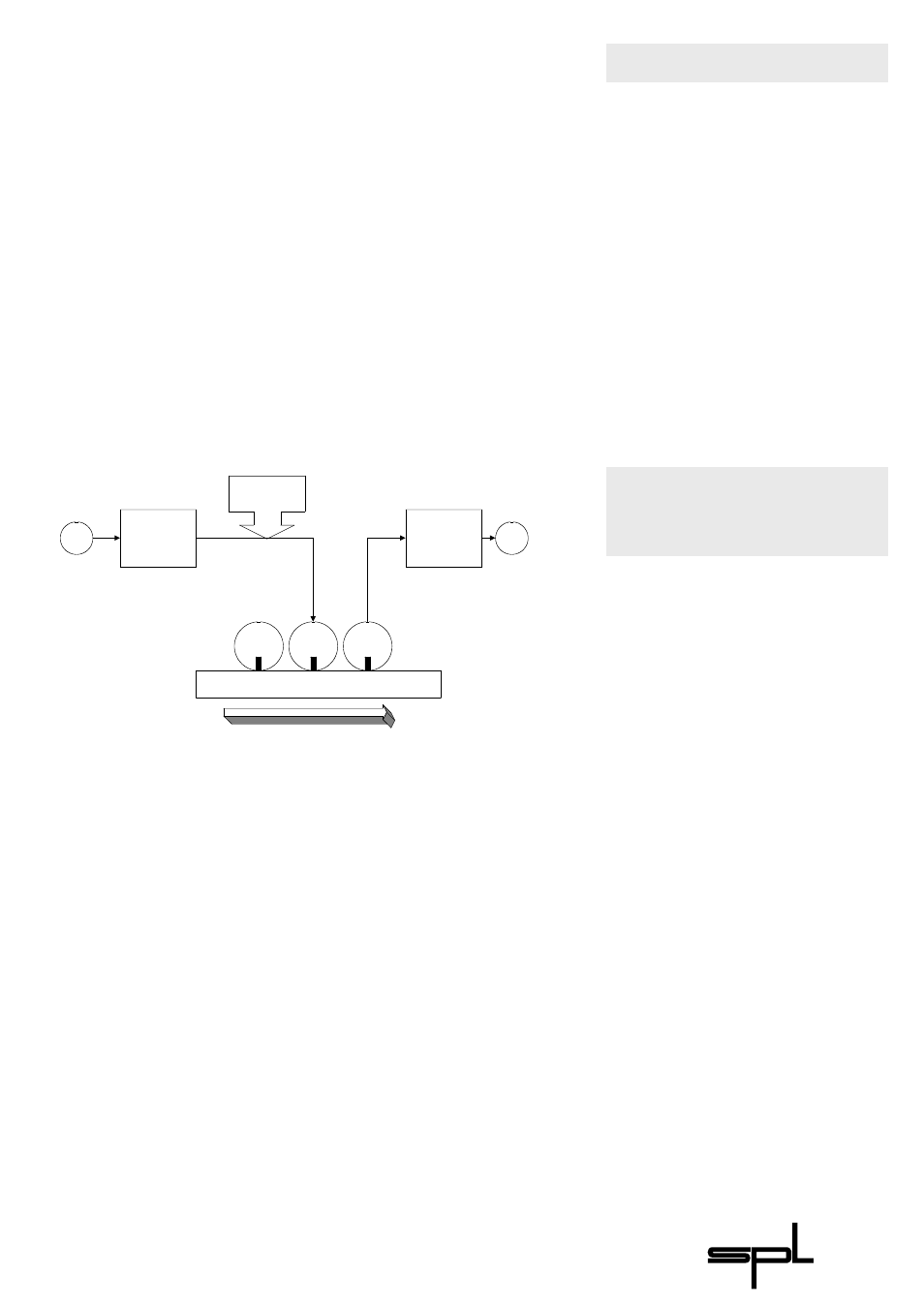
Magnetic Tape:
Hysteresis Curve
Record
Head
Erase
Head
Playback
Head
Input
High frequency
Bias Current
Record
Equaliser
Playback
Equaliser
Output
All controls are in the start-off positions:
I
NPUT
G
AIN
0, D
RIVE
0, HF-A
DJUST
0,
O
UTPUT
G
AIN
0, T
APE
S
PEED
15
1.
Press A
CTIVE
. LED illuminates.
2. Increase
the
D
RIVE
-value to saturate the “virtual” tape.
Set D
RIVE
to about 6. If the output level increases, use
the O
UTPUT
G
AIN
control to compensate for the increase.
3.
If more saturation is wanted, it may be necessary to
reduce the I
NPUT
G
AIN
slightly to prevent clipping.
4.
Use the HF-A
DJUST
control to create the typical high
frequency damping effect (negative values) or increase
the high frequencies and harmonical content (positive
values).
The audio signal that passes the input electronics of an
analogue tape machine is first processed by the recording
equalizer. The high frequencies are boosted to compensate for
the level loss of those frequencies during magnetization and to
improve the signal to noise ratio.
A high frequency bias current is afterwards added to the
signal to linearize the non linear hysteresis transfer curve of the
magnetization.
The recording head converts the current of the input signal
into a magnetic field. The field magnetizes the magnetic
particles on the passing tape. This process is physically complex
and non linear. Hysteresis curves lead to the typical saturation
effect and to the effect of short wavelength losses.
The playback head converts the magnetic field of the passing
tape back into current and voltage. The playback equalizer has
a normed frequency response (e.g. CCIR/NAB) which makes
the overall freqency response flat and compensates for the
additional boost in the recording equalizer.