3 external interfaces – Sanyo SANUPS E11A102A User Manual
Page 14
− 11 −
EXT.
BATT
MAIN SW
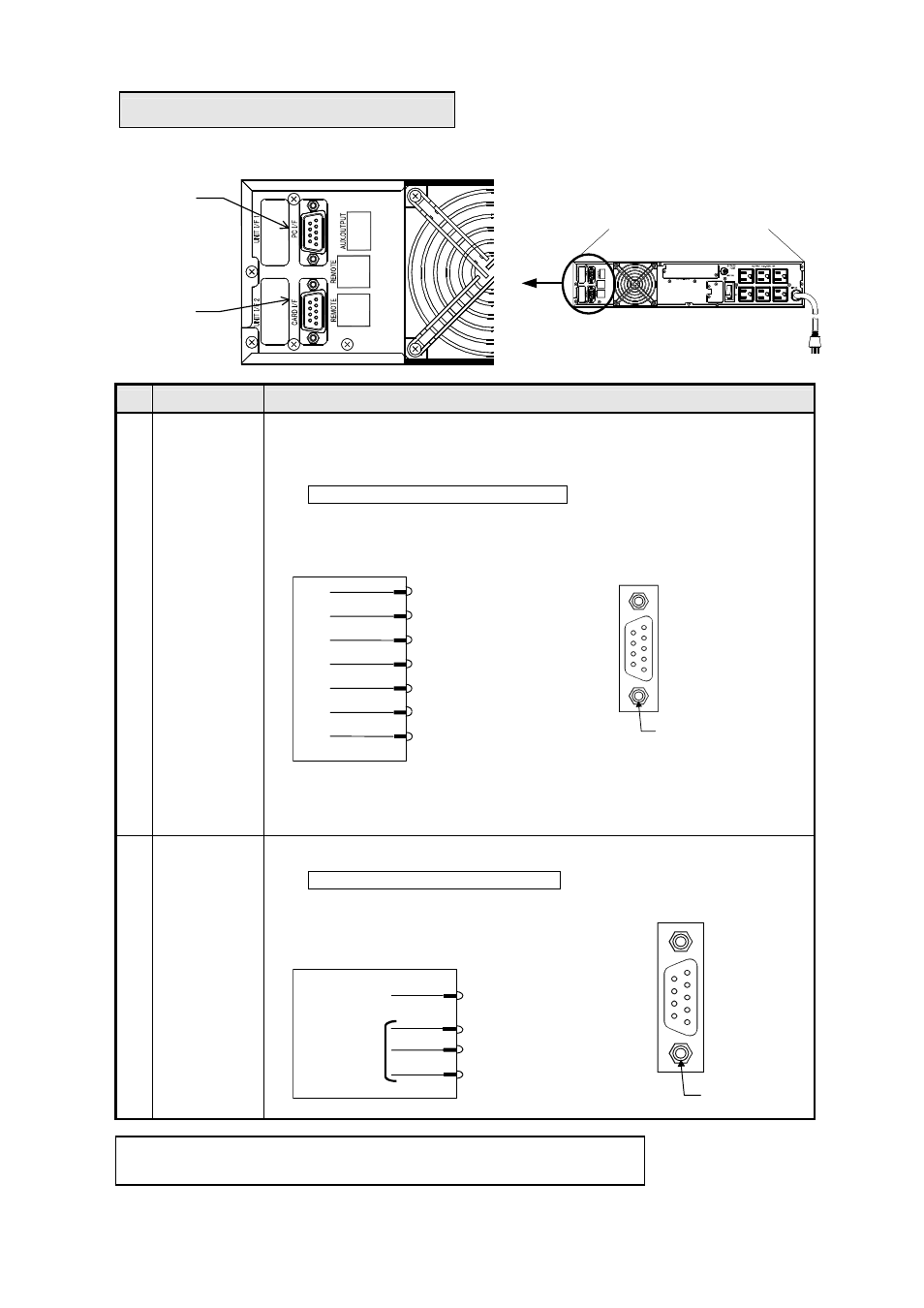
5.3 External Interfaces
UPS back panel
No.
Name
Function
①
PC I/F
(PC interface)
(RS-232C)
Allows you to control the UPS from a computer (PC or workstation) by using the
supplied power management software. Install the power management software (*2)
on the computer, and connect the computer to the UPS with the supplied network
cable.
Interface mode (*1): Workstation mode
(*1): Use the controls on the front panel to set the interface mode. For more
information, see item ⑤ PC Interface mode in §10.1 “Setup Menu Item List”.
(*2): For more information, refer to the User Guide in the CD-ROM of the
SANUPS SOFTWARE.
②
CARD I/F
(Card interface)
Allows you to connect an optional Sanyo LAN interface card.
Interface mode (*1): Workstation mode
Note
This connector is for use with Sanyo option cards only.
Note
The CARD I/F and PC I/F connectors cannot be used at the same time.
②
①
2
RXD (in)
3
TXD (out)
5
(COM)
1
7V,1A/Option power
Cannotbe
used with
other than
Sanyo
option cards.
⑨
⑧
⑦
⑥
⑤
④
③
②
①
D-sub 9-pin (female)
Fixing screw
inch
2
RXD
3
TXD
5
GND
4
DTR
6
DSR
8
CTS
7
RTS
⑥
⑦
⑧
⑨
①
②
③
④
⑤
D-sub9-pin (male)
Fixing screw
inch