85464359982001(usa eco-i_5) – Sanyo R410A User Manual
Page 56
56
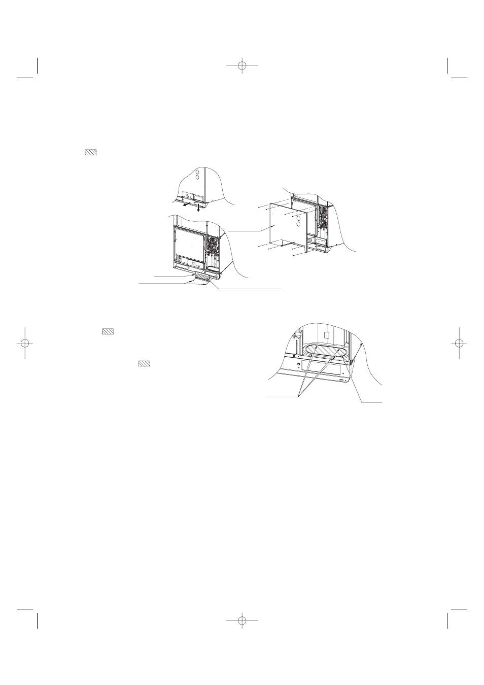
Fig. 4-6
Remove 2 screws
Tubing cover
Bottom
Front
Remove 11 panel
screws from front
panel
Use cutting pliers or similar
tool to cut cover out
Fig. 4-5
Indentation
(4 locations)
Slit hole
4-3. Routing the Tubing
● The tubing can be routed out either from the front or from the bottom. (Fig. 4-6)
● The connecting valve is contained inside the unit. Therefore, remove the front panel. (Fig. 4-6)
(1) If the tubing is routed out from the front, use cutting pliers or a similar tool to cut out the tubing outlet slit (part indicated
by
) from the tubing cover. (Figs. 4-5 and 4-6)
(2) If the tubing is routed out from the bottom, remove the
slit part (
).
● Use a drill bit approximately 13/64 dia. to create holes at
the 4 slit hole indentations (openings).
● Punch out the slit part (
).
● Be careful not to damage the base plate.
07-007 W-2WAY_II_NA 1/23/07 6:09 PM Page 56
- ECO-i WCHDZ20053 (2 pages)
- CL0951 (3 pages)
- ECO G SPW-GU075XH (9 pages)
- CM1972 (99 pages)
- CR365GX56 (1 page)
- 42XS32A (3 pages)
- CL2432A (3 pages)
- 9 (2 pages)
- KH3072R / C3072R (180 pages)
- CH0971 (2 pages)
- 26UW72R (2 pages)
- C2432 (17 pages)
- CR1304GDZH8 (1 page)
- KH2672R (48 pages)
- ECOi C0905DXHN8 (10 pages)
- CH1251 (98 pages)
- 30KS32A (3 pages)
- Concealed Duct & Heat Pump H 13.9-14.9 SEER (2 pages)
- 42TLS32A (3 pages)
- CL2462R (58 pages)
- C1251 (83 pages)
- DHX3652 (114 pages)
- 42XHW72R (2 pages)
- 09KS71 (2 pages)
- C3632A (3 pages)
- 18KS72 (2 pages)
- 12XS71 (2 pages)
- ECO R410A (48 pages)
- KS2472 (117 pages)
- INVERTER SPLIT SYSTEM 8.53E+13 (24 pages)
- C3082 (104 pages)
- KHHS2672R (4 pages)
- CHX06052 (246 pages)
- CL1211 (16 pages)
- CH3082 (109 pages)
- Indoor Unit thx1852 (4 pages)
- 42TW72R (2 pages)
- KHS1872 (111 pages)
- C4232 (66 pages)
- CHDZ14053 (265 pages)
- CL0971 (4 pages)
- CHDX14053 (243 pages)
- 09KS51 (3 pages)
- 12RLS11 (3 pages)
- CL1852 (81 pages)