Pulse output module diagnostic led’s, Specifications – Siemens IGWIPS200-1 User Manual
Page 33
IGWiPS200-1
PULSE OUTPUT MODULE DIAGNOSTIC LED’S
There are 3 diagnostic LED’s on the pulse output module:
Status LED: On solid when I/O is functional and flashing if there is a conflict with another module.
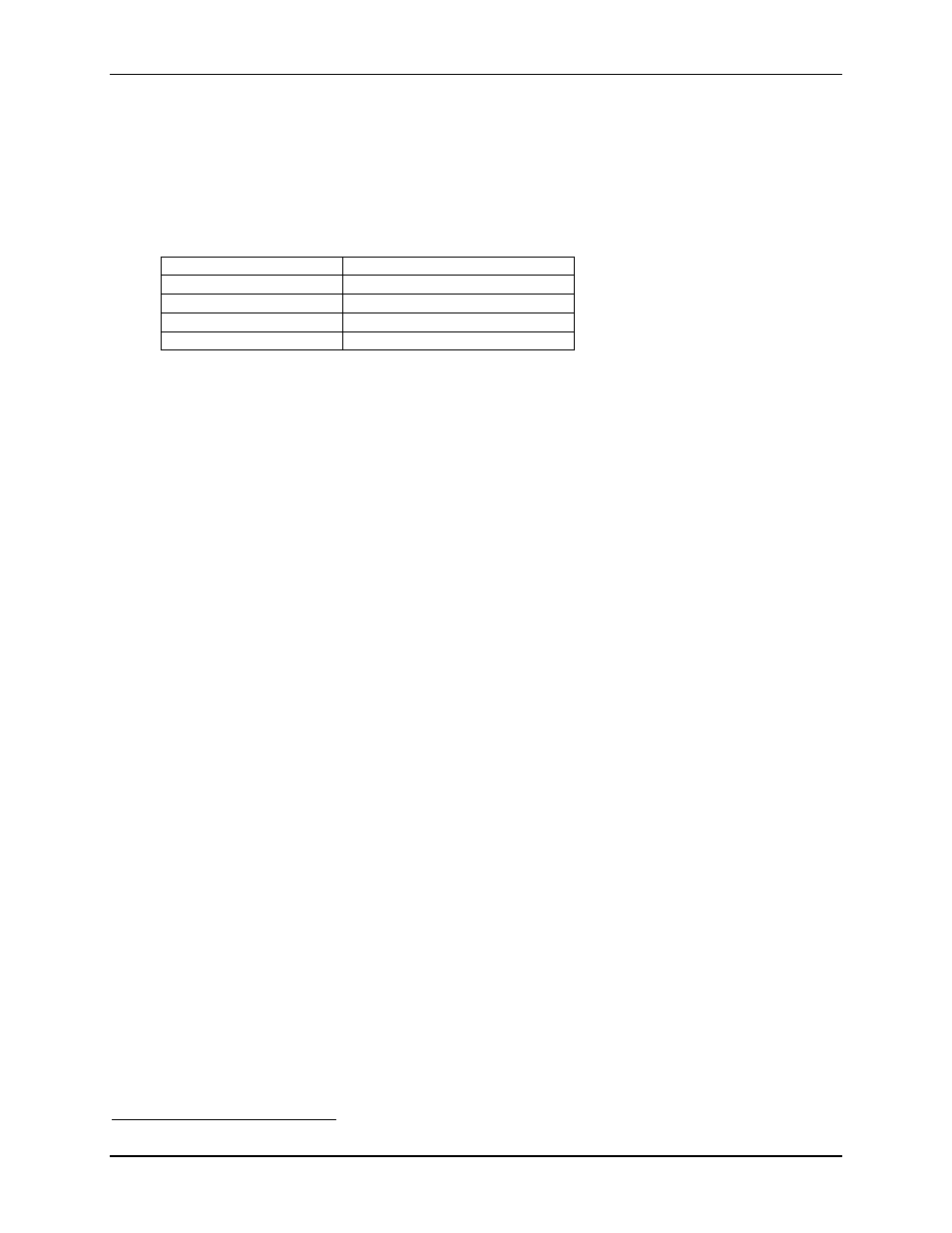
Pulse Input 1 and 2 LEDs: These lights will flicker at a varying frequency depending on the frequency of
pulses being generated:
Frequency Range (Hz)
LED Flashing Frequency (Hz)
1 ≤ frequency ≤ 10
1
10 < frequency ≤ 100
4
100 < frequency ≤ 1000
8
1000 < frequency ≤ 32K
On solid
SPECIFICATIONS
Transceiver
Frequency .............................................................902 to 928 MHz industrial, scientific, and medical (ISM) band
Technology...........................................................Frequency Hopping Spread Spectrum
Power Input ..........................................................9-30 Vdc; reverse polarity and surge protected
Power Consumption .............................................75 mA (average), 200 mA (peak) @ 24 Vdc during transmission
(plus I/O modules), 5A (maximum)
Inputs
Analog ...........................................................1, 4 to 20 mA (16-bit, 125 Ohms impedance
Digital............................................................2, 5 to 36 Vac/Vdc (for 120 Vac digital inputs use relays to convert
to specified voltage levels; consult factory for relay options)
Outputs
Analog ...........................................................1, 4 to 20 mA, 12-bit resolution, short circuit protected
Digital............................................................2,
250 Vac / 30 Vdc, 2A dry contact
RF
Link .........................................................1, 250 Vac / 30 Vdc, 2A dry contact
Repeatability (4-20 mA Current Loop) ................0.02%
Accuracy (4-20 mA Current Loop) ......................0.2% full scale
Transmitter Power Output ....................................1 Watt (30 dBm)
Range
Standard Omnidirectional Antenna ...............600 to 1000 feet (183m to 305m) in-plant, obstructed LOS
Optional Omnidirectional Antenna ...............4 to 5 miles (6.5 km to 8 km) clear LOS, flat terrain, raised antenna
Optional Yagi Antenna..................................15 to 20 miles (24 km to 32 km) clear LOS, flat terrain,
professional propagation study and installation
Antenna Connector ...............................................MCX female, 50 Ohms
Operating Temperature Range..............................-40°C to 70°C (-40°F to 158°F)
Humidity...............................................................20% to 90% non-condensing
Dimensions ...........................................................4.5" x 3.9" x 0.9" (114 mm x 99 mm x23 mm)
Faceplate Label Color...........................................White
Weight ..................................................................5.3 oz (150g)
Environmental ......................................................NEMA 1, equivalent to IP 20
Approvals
USA...............................................................FCC
47CFR15.247
Canada...........................................................ISC RSS 210
UL and CUL..................................................Class I, Div. 2, Groups A, B, C, D; Temp. Code T5
CSA ...............................................................Approved
6
LOS – Line of Sight between transmitting and receiving antennas
May 2007
31