Wiring and installation, Noise-cancellation, Polarity – Shure 562 User Manual
Page 2: Accessories, Replacement parts, Architects' specification
2
WIRING AND INSTALLATION
The 562 may be wired for balanced or unbalanced oper-
ation. For unbalanced operation, the white cable wire is con-
nected to the audio input, the black cable wire is connected
to the audio ground, and the shield is connected to the chas-
sis ground. See Table 1.
For balanced operation, the white cable wire is connected
to the audio input positive (+), the black wire is connected to
the audio negative (–), and the shield is connected to the
chassis ground. See Table 1.
Once mounted to a stand or gooseneck, the 561 can be
locked in place by tightening the setscrew over the mounting
threads.
NOISE-CANCELLATION
The Model 562 cancels noise because of its frequency
response and distance discrimination. By performing
optimally in the frequency range between 100 and 6,000 Hz,
the 562 avoids picking up noise outside this range. Its
design also utilizes acoustic interference to reject sounds
originating from a distance in favor of sounds originating
from a near source.
To obtain optimal noise-canceling performance, the
model 562 must be “close talked.” Place your lips as close
to the microphone grille as comfort will permit. A distance
between roughly 6 mm and 25 mm (1/4 in. and 1 in.)
provides the greatest discrimination between speech and
ambient noise.
POLARITY
If multiple microphones are in use simultaneously, they
should be wired with common polarity. To determine
whether two microphones have the same polarity, talk or
sing into both while holding them 8 to 10 cm. apart. The
volume of the amplified sound should remain the same
whether the speaker is talking directly into either
microphone, or is positioned equally between them. If the
volume drops when talking into both microphones, they are
wired with different polarity. The polarity of individual
microphones may also be checked with polarity-checking
devices.
To reverse the polarity of the 562, the BLACK and WHITE
leads must be interchanged either at the microphone car-
tridge (See Table 1) or at the amplifier or mixer input. This
should be performed by your dealer, the Shure Factory Ser-
vice Department, or other qualified service personnel.
ACCESSORIES
Furnished
Allen Wrench (No. 4) .......................................... 80A67
Optional
Gooseneck (12 in., 18 in.) ............................. G12, G18
Gooseneck, Side vent (6 in., 18 in.) ........... G6A, G18A
Gooseneck, Side vent,
3-pin connector.............................. G12-CN, G18-CN
Mounting Flange..................................................... A12
Heavy-Duty Mounting Flange ............................ A13HD
Windscreen............................................ A58WS Series
REPLACEMENT PARTS
Cartridge................................................................. R90
Screen and Grille Assembly ........................ 90FR2600
Cable ................................................................ 70A292
Case ............................................................. 31A1238A
ARCHITECTS' SPECIFICATION
The microphone shall be a moving coil (dynamic) type
with a frequency response of 100 to 6,000 Hz. The unit shall
be a noise-canceling type. The microphone shall be low
impedance with a rated impedance of 150 ohms for connec-
tion to microphone inputs rated 19 to 300 ohms. The micro-
phone output shall be –64 dBV/Pa. It shall be equipped with
a non-detachable 1.2 m (4 ft.) cable and shall be threaded for
mounting on a stand or gooseneck with a 5/8"–27 thread.
The overall dimensions of the microphone shall be 67 mm
(2–21/32 in.) in length and 34.5 mm (1–3/8 in.) in diameter.
The microphone shall be the Shure Model 561 or equivalent.
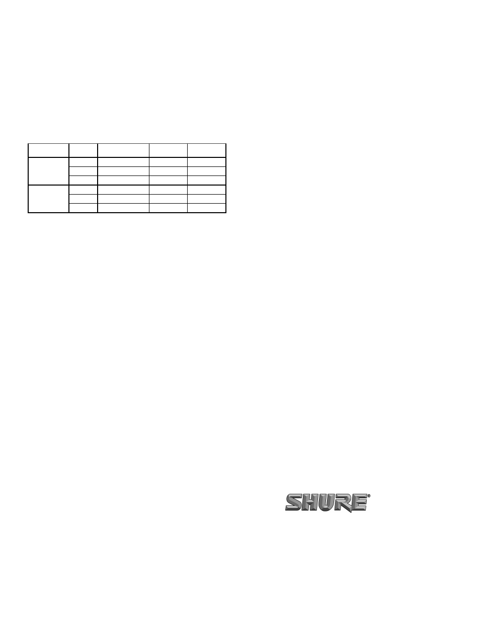
Table 1. Cable-to-Connector Wiring
INPUT TYPE
WIRE
COLOR
FUNCTION
XLR
CONNECTOR
1/4 IN. PHONE
PLUG
UNBALANCED
WHITE
AUDIO
PIN 2
TIP
BLACK
AUDIO GROUND
PIN 3
SLEEVE
SHIELD
CHASSIS GROUND
PIN 1
SLEEVE
BALANCED
WHITE
AUDIO +
PIN 2
TIP
BLACK
AUDIO –
PIN 3
RING
SHIELD
CHASSIS GROUND
PIN 1
SLEEVE
SHURE Incorporated http://www.shure.com
United States, Canada, Latin America, Caribbean:
5800 W. Touhy Avenue, Niles, IL 60714-4608, U.S.A.
Phone: 847-600-2000 U.S. Fax: 847-600-1212 Intl Fax: 847-600-6446
Europe, Middle East, Africa:
Shure Europe GmbH, Phone: 49-7131-72140 Fax: 49-7131-721414
Asia, Pacific:
Shure Asia Limited, Phone: 852-2893-4290 Fax: 852-2893-4055