Installation - wiring, Installation step 3, Wiring – Soundstream Technologies 1002 User Manual
Page 8: Ground, Remote turn-on, Rub/con amplifier fuse values signal cable, Speaker cable, Power and, Circuit breakers and fuses
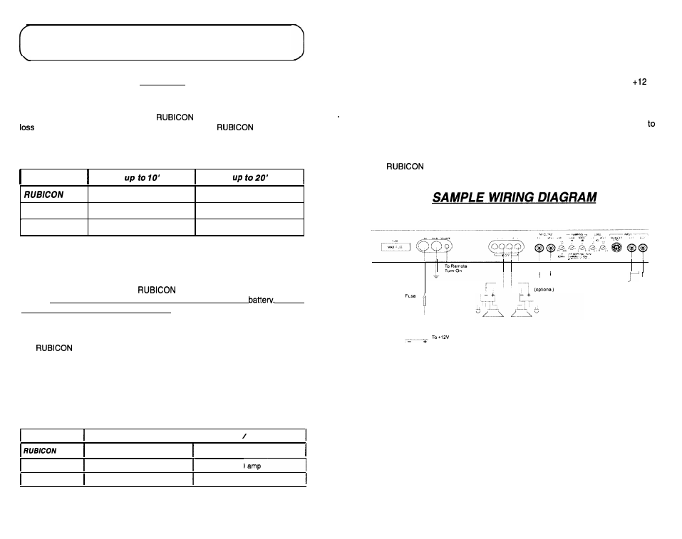
INSTALLATION STEP 3
WIRING
POWER
AND
GROUND
To ensure maximum output from your
amplifier,
use
high quality, low-
power and ground cables and connections. The
amplifiers will
accept up to 4 gauge power and ground cables. Determine from the chart below
the minimum gauge power and ground wire for your application.
REMOTE TURN-ON
Connect the “Remote” line to the turn-on lead from the source unit. When
Volts is received, the amplifier will turn on.
Use a high quality cable that will be easy to install and has minimal signal loss
guarantee optimum performance.
The
amplifiers will accept up to 8 gauge speaker cable. Use a high
quality, flexible, multi-strand cable for best performance and longevity.
RUB/CON Amplifier Fuse Values
SIGNAL CABLE
502
4 or 8 gauge
4 gauge only
RUB/CON 702
4 or 8 gauge
4 gauge only
RUB/CON 1002
4 gauge only
4 gauge only
Amplifier Fuse
I
Battery Fuse Circuit Breaker
502
(2) 30
amp
automotive
80 amp
RUB/CON 702
60 amp Maxi-fuse
80 amp
SPEAKER CABLE
CIRCUIT BREAKERS AND FUSES
EXTERNAL
Like all audio components, the
amplifiers must be fused near the
battery. A fuse or circuit breaker must be located within 18” of the
This will
at the
prevent a fire in the event of a shorted cable. See the chart below to determine the
Battery
correct fuse value.
INTERNAL
The
amplifiers are fused with an automotive-type or Maxi-fuse. In the
event of a blown power supply fuse(s), replace with the correct value fuse found in
the chart below. Never replace the fuse with a higher value than what is sup-
plied. This may result in amplifier damage and will void the warranty1
Battery
Terminal
To Chassis
Ground
To 2nd
Amplifier
SPEAKERS
[Head Unit
RUB/CON 1002
80 amp Maxi-fuse
100
a m p
14
15