Sanyo C1211 User Manual
Page 13
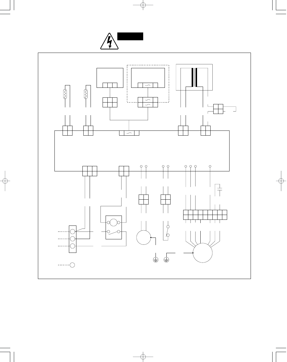
● Electric Wiring Diagram
Indoor Unit: RS1211
8
WM – 700703
1 2
1 2
DP
DP1
TO OUTDOOR UNIT
Power transformer
1 2
1 2
1
7
BLK
1 2
1 2
BLK
1 2 3
1 2 3
1 2 3
1
9
1
9
1
10
1 2
1 2
WHT
WHT
1 2
1 2
BRN
BRN
BRN
1
G
2
3
1 2 3
1 2 3
1 2
1 2
DP2
1 2
1 2
RED
RED
RED
RED
FS1 FS2
1 2
1 2
BLK
H M
1 2
1 2
BLU
VLT
BLU
VLT
L
3
3
4
4
5
5
FM2
6
6
GRY
7
7
BRN
8
8
PNK
9
9
FMI
GRY
BRN
PNK
CM
2P (BLK)
SUP
3P (BLK)
TR
RS1211RW
Switch assy
IND lamp assy
Thermistor
Connector
3P (WHT)
Connector
9P (WHT)
2P (RED)
TH1
2P (BLK)
TH2
10P (WHT)
2P (RED)
PRY
2P (WHT)
SEC
Controller (POW-RS1211)
Connector
2P (WHT)
S
P
TH1 (Coil)
TH2 (Room)
Capacitor
C1
RY
Terminal
plate (3P)
NO COM
2
1
Compressor relay
Drain pump
Indoor fan motor
Connector
9P (BLK)
Connector
2P (RED)
Connector
2P (WHT)
Float switch
Earth
terminals
WHT
BRN
BLK
WHT
ORG
ORG
FS
BRN
BLK
BLK
FM
BLK
ORG
RED
GRN
GRN
BLK
BLK
YEL
8
WARNING:
To avoid electrical shock hazard, be sure to
disconnect power before checking, servicing
and/or cleaning any electrical parts.