Sears 486.248463 User Manual
Page 11
11
FIGURE 19
RIGHT FRONT CORNER VIEW
• Coat the top of the ring around the dis charge open ing
with general purpose grease. See fi gure 19.
• Place the discharge chute (facing forward) onto the
discharge opening, aligning the crank rod spiral with
the notch es in the chute fl ange.
• Attach the three chute keep ers (right side up as
shown in fi gure 19) and the anti-rotation bracket to the
bottom of the chute fl ange. Use six 1/4" x 1" hex bolts,
1/4" fl at wash ers and 1/4" fl anged lock nuts.
Tighten
carefully so that the plastic parts are not deformed.
See fi gure 19.
• Place the plastic grip onto the back end of the anti-
rotation bracket. See fi gure 19.
• Position the chute crank assembly so that the crank
rod spiral does not rub the bottoms of the notch es in
the chute fl ange and then
tighten the nuts left loose
in fi gure 19.
• Check if the crank rod rotates the chute freely. If not,
loosen by 1/4 turn each the six fl anged nuts holding
the chute keepers to the chute fl ange.
FIGURE 18
LEFT SIDE VIEW
CHUTE CRANK
ASSEMBLY
5/16" LOCK
WASHER
5/16" HEX NUT
5/16" x 1"
CARRIAGE BOLT
5/16"FLAT
WASHER
ANTI-ROTATION
BRACKET
CHUTE
KEEPER
1/4" FLANGED
LOCK NUT
1/4" x 1"
HEX BOLT
PLASTIC
GRIP
FLANGE
GREASED
SURFACE
1/4" FLAT
WASHER
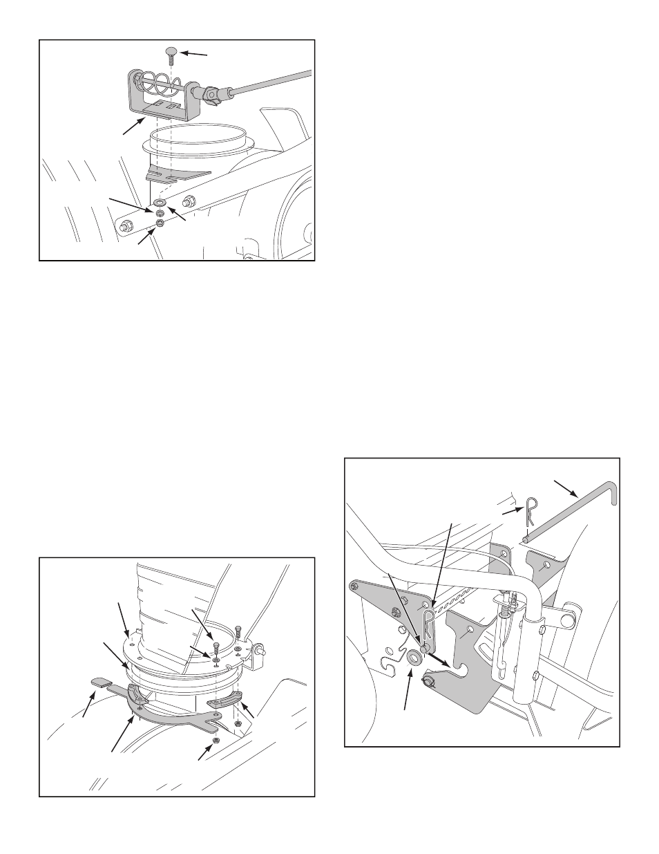
MOUNTING SNOW THROWER TO TRACTOR
NOTE: The help of another person may be re quired to
mount the snow thrower to the front of the tractor.
• Place the tractor and snow thrower on a fl at, level
surface.
• Remove the plastic tie from the auger belt and extend
the belt out behind the snow thrower, making sure the
belt remains as sem bled around the top of the large
auger drive pulley and passing un der neath the two
side idler pulleys.
• Align the tractor behind the snow thrower.
• Remove the attachment pin from the snow thrower.
• Squeeze the release trigger on the lift handle and
raise the handle out of the locked position. (If the
handle will not release out of the locked position,
refer to the Service and Adjustments section of this
manual.)
• Grasp the round bar just behind the auger drive pulley
and lift up to align the rear mounting notches on the
snow thrower with the mount ing pins on the tractor.
Slide the pins into the notches.
HINT: If you are unable to fi t the mounting pins into
the notches, try placing 1" or 2" blocks of wood under
the front skid shoes on the snow thrower.
• Assemble a 3/4" washer and a 1/8" hairpin clip to
each mounting pin.
• Secure the snow thrower to the tractor using the
at tach ment pin and 1/8" hairpin clip. Insert the
attachment pin from the left side. See fi gure 20.
FIGURE 20
RIGHT SIDE VIEW
3/4" FLAT
WASHER
ATTACHMENT PIN
1/8" HAIRPIN CLIP
MOUNTING
PIN