Refrigerant flow diagram – Sanyo STB1220C1 User Manual
Page 12
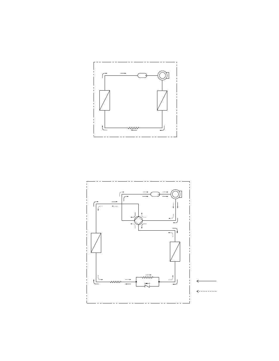
4. REFRIGERANT FLOW DIAGRAM
C
o
m
p
re
s
s
o
r
4-way
valve
Accumulator
O
u
td
o
o
r
h
e
a
t
e
x
c
h
a
n
g
e
r
In
d
o
o
r
h
e
a
t
e
x
c
h
a
n
g
e
r
Cooling cycle
Heating cycle
Capillary
tube
Capillary
tube
Check
valve
Model
STB0823H1
Compressor
Accumulator
C
o
n
d
e
n
s
e
r
E
v
a
p
o
ra
to
r
Capillary
tube
Models
STB0810C1
STB1010C1
STB1020C1
STB1220C1
STB0811C1
STB1023C1
STB1123C1
8