Datasheet – SMSC LAN9514 User Manual
Page 13
USB Hub with Integrated 10/100 Ethernet Controller
Datasheet
SMSC LAN9514
13
Revision 1.0 (04-20-09)
DATASHEET
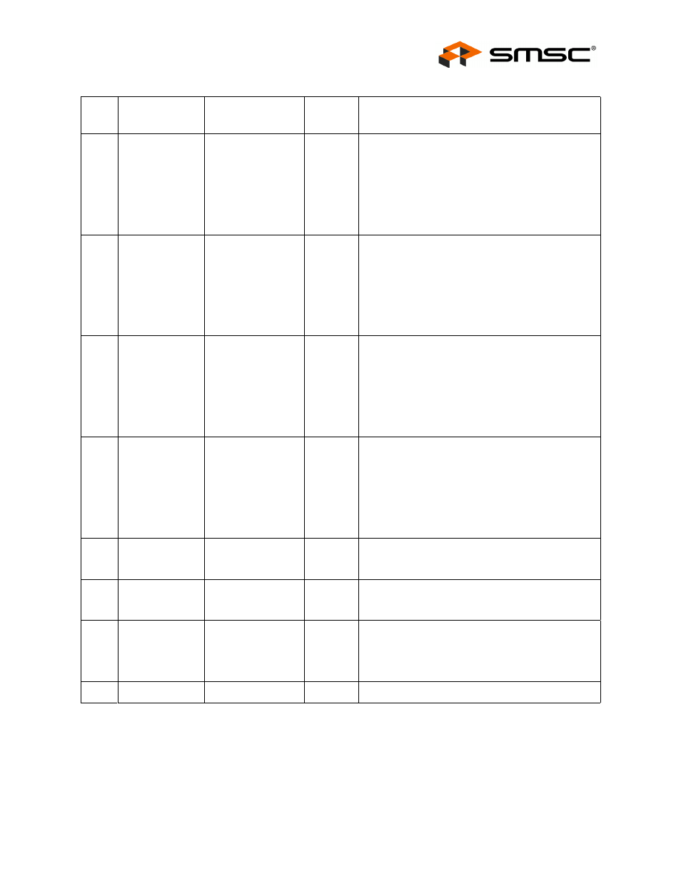
1
USB Port Power
Control 2
PRTCTL2
IS/OD12
(PU)
When used as an output, this pin enables power to
downstream USB peripheral 2.
When used as an input, this pin is used to sample
the output signal from an external current monitor
for downstream USB peripheral 2. An overcurrent
condition is indicated when the signal is low.
for additional information.
1
USB Port Power
Control 3
PRTCTL3
IS/OD12
(PU)
When used as an output, this pin enables power to
downstream USB peripheral 3.
When used as an input, this pin is used to sample
the output signal from an external current monitor
for downstream USB peripheral 3. An overcurrent
condition is indicated when the signal is low.
for additional information.
1
USB Port Power
Control 4
PRTCTL4
IS/OD12
(PU)
When used as an output, this pin enables power to
downstream USB peripheral 4.
When used as an input, this pin is used to sample
the output signal from an external current monitor
for downstream USB peripheral 4. An overcurrent
condition is indicated when the signal is low.
for additional information.
1
USB Port Power
Control 5
PRTCTL5
IS/OD12
(PU)
When used as an output, this pin enables power to
downstream USB peripheral 5.
When used as an input, this pin is used to sample
the output signal from an external current monitor
for downstream USB peripheral 5. An overcurrent
condition is indicated when the signal is low.
for additional information.
1
External USB
Bias Resistor
USBRBIAS
AI
Used for setting HS transmit current level and on-
chip termination impedance. Connect to an
external 12K 1.0% resistor to ground.
1
USB PLL +1.8V
Power Supply
VDD18USBPLL
P
Refer to the LAN9514 reference schematics for
additional connection information.
1
Crystal Input
XI
ICLK
External 25 MHz crystal input.
Note:
This pin can also be driven by a single-
ended clock oscillator. When this method
is used, XO should be left unconnected
1
Crystal Output
XO
OCLK
External 25 MHz crystal output.
Table 2.4 USB Pins (continued)
NUM
PINS
NAME
SYMBOL
BUFFER
TYPE
DESCRIPTION