Table 2.4 usb pins, Datasheet – SMSC LAN9514 User Manual
Page 12
USB Hub with Integrated 10/100 Ethernet Controller
Datasheet
Revision 1.0 (04-20-09)
12
SMSC LAN9514
DATASHEET
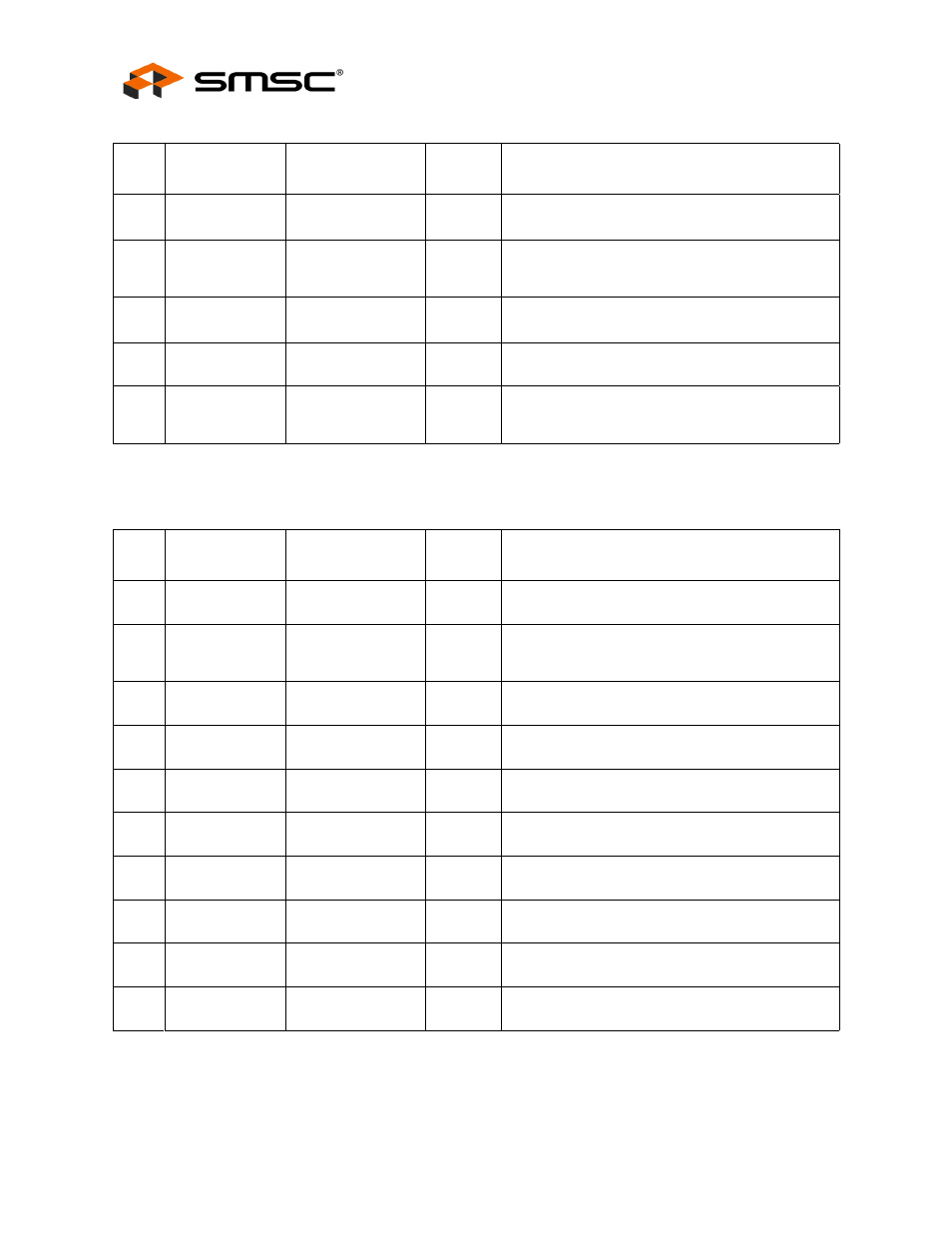
1
Test 2
TEST2
-
Used for factory testing, this pin must always be
connected to VSS for proper operation.
1
Test 3
TEST3
-
Used for factory testing, this pin must always be
connected to VDD33IO for proper operation.
1
24 MHz Clock
Enable
CLK24_EN
IS
This pin enables the generation of the 24 MHz
clock on the CLK_24_OUT pin.
1
24 MHz Clock
CLK24_OUT
08
This pin outputs a 24 MHz clock that can be used
a reference clock for a partner hub.
1
Test 4
TEST4
-
Used for factory testing, this pin must always be left
unconnected.
Table 2.4 USB Pins
NUM
PINS
NAME
SYMBOL
BUFFER
TYPE
DESCRIPTION
1
Upstream
USB DMINUS 0
USBDM0
AIO
Upstream USB DMINUS signal.
1
Upstream
USB
DPLUS 0
USBDP0
AIO
Upstream USB DPLUS signal.
1
Downstream
USB DMINUS 2
USBDM2
AIO
Downstream USB peripheral 2 DMINUS signal.
1
Downstream
USB DPLUS 2
USBDP2
AIO
Downstream USB peripheral 2 DPLUS signal.
1
Downstream
USB DMINUS 3
USBDM3
AIO
Downstream USB peripheral 3 DMINUS signal.
1
Downstream
USB DPLUS 3
USBDP3
AIO
Downstream USB peripheral 3 DPLUS signal.
1
Downstream
USB DMINUS 4
USBDM4
AIO
Downstream USB peripheral 4 DMINUS signal.
1
Downstream
USB DPLUS 4
USBDP4
AIO
Downstream USB peripheral 4 DPLUS signal.
1
Downstream
USB DMINUS 5
USBDM5
AIO
Downstream USB peripheral 5 DMINUS signal.
1
Downstream
USB DPLUS 5
USBDP5
AIO
Downstream USB peripheral 5 DPLUS signal.
Table 2.3 Miscellaneous Pins (continued)
NUM
PINS
NAME
SYMBOL
BUFFER
TYPE
DESCRIPTION