Figure 3, Figure 4, Variable flame height adjustment – Superior SLDVT-40NE User Manual
Page 9
9
NOTE: DIAGRAMS & ILLUSTRATIONS ARE NOT TO SCALE.
SUPERIOR
®
DIRECT-VENT GAS FIREPLACES • MODELS SLDVT-30/35/40/45 • CARE AND OPERATION INSTRUCTIONS
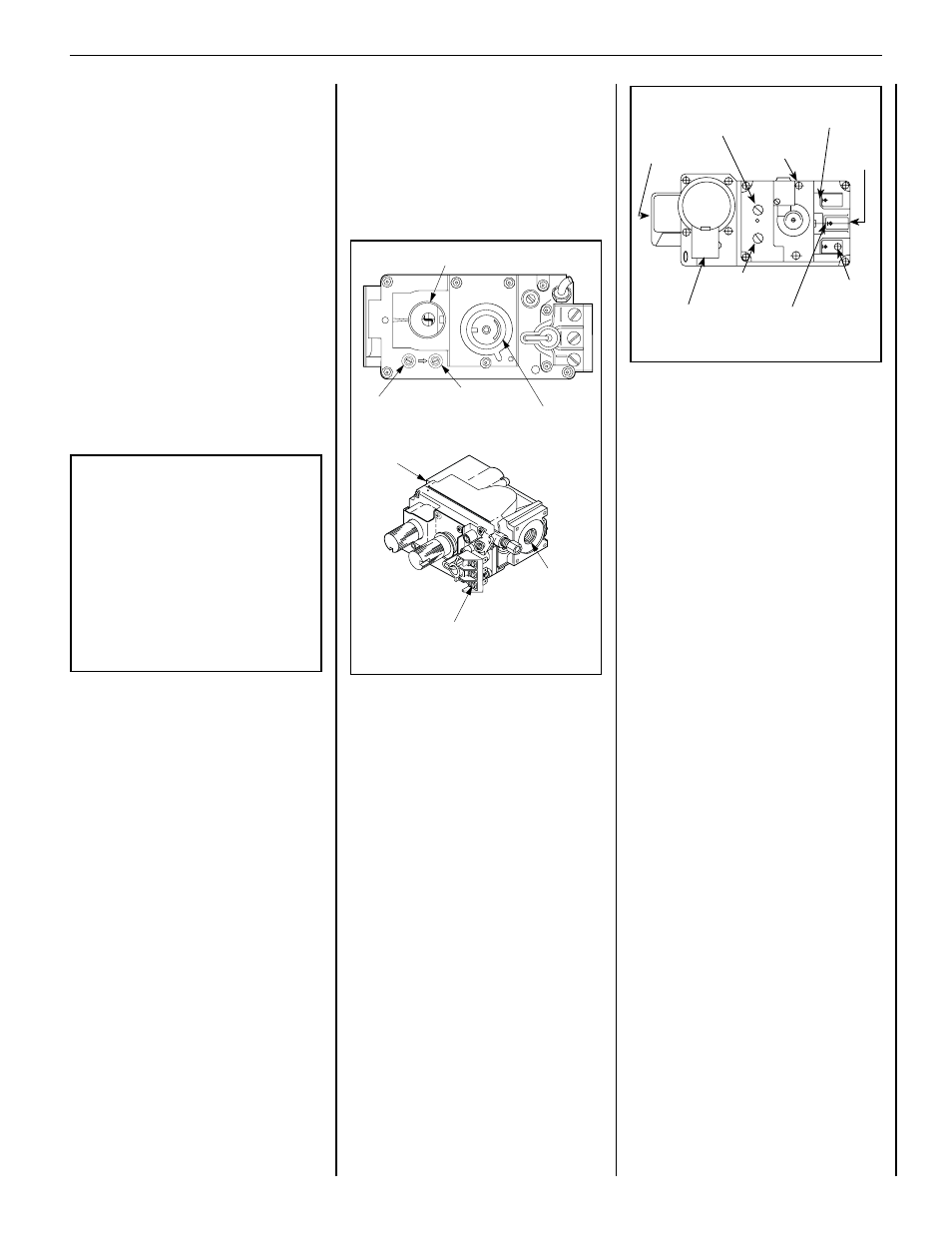
Figure 3
- SIT Millivolt Gas Valve
Variable Flame
Height Adjustment
Manifold Pressure
Port
Inlet
Pressure
Port
Main Gas Control Knob
H I
LO
W
TPTH
TP
TH
PIL
OT
PI
LO
T
ON
it
OFF
IN
OUT
Gas Inlet
Terminals TPTH, TP and TH
Gas
Outlet
Figure 4
- Dexen Electronic Gas Valve
Variable Flame
Height Adjustment
Manifold Pressure
Port
Inlet
Pressure
Port
Main Gas Control Knob
H I
LO
W
TPTH
TP
TH
PIL
OT
PI
LO
T
ON
it
OFF
IN
OUT
Gas Inlet
Terminals TPTH, TP and TH
Gas
Outlet
Supply Gas
Inlet
Pressure-Tap
(Manifold)
Regulator
Mounting
Screw
Burner Stage
Terminal
Gas
Outlet
To Burner
Ground (TP)
Pilot Stage
Terminal
Pilot Gas Outlet
Pressure-Tap
(Inlet)
PILOT
OUT
VENT
LO
TH TP
TH
TP
HI
IN
IN
Note: It is recommended that batteries not
be installed in the battery holder until a power
outage, or if the appliance is to be operated
solely with two (2) "D" batteries.
Refer to the Lighting Instructions on Page 24 to
light the appliance in the event of a power failure.
TO LIGHT THE APPLIANCE
DURING A POWER OUTAGE:
• Install batteries in battery pack.
• Turn unit mounted switch or wall switch
to the ON Position.
• Unit should spark at pilot and light.
• Operate Normally.
• Replace batteries if needed.
• After power is restored, remove batteries.
Variable Flame Height Adjustment
All millivolt and electronic appliances are
equipped with a variable gas control valve. Flame
height for these models may be adjusted through
a range between fixed low and high settings while
the appliance is in operation. Adjust the flame
height as desired after lighting the appliance by
rotating the variable adjustment control knob
(HI/LO) located on the front of the valve (refer
to Figures 3 and 4).
Electronic Appliances
To light electronic appliances refer to the detailed
lighting instructions found on Pages 24 and
25 of these instructions. Electronic appliance
lighting instructions may also be found on the
pull out lighting instruction labels attached to
the gas control valve.
If your electronic appliance is equipped with an
optional remote wall switch or remote control
kit the appliance main burner may be turned on
and off with the wall switch or remote control.
If your electronic appliance is not equipped
with a wall switch or remote control, the main
burner must be turned off and on with a gas
control switch located in some other location
by the installer. Contact the installer for direc-
tions. Check batteries, if installed, routinely
(ever three months).