10/15-hour maintenance, Cutter blade adjustment, Hour maintenance – Shindaiwa 68800-94313 User Manual
Page 12
1
10/15-Hour Maintenance
CAUTION!
Before removing the spark plug, clean
the area around the plug to prevent dirt
and dust from getting into the engine’s
internal parts.
Every 10 to 15 hours
of operation:
n
Remove and clean the spark plug.
See Figure 19. Adjust the spark plug
electrode gap to 0.04-inch (0.6 mm).
If the plug must be replaced, use only:
NGK CMR5H or equivalent.
Clean the spark
plug and check
the gap at the
electrode.
0.024 inch
(0.6 mm)
n
Lubricate the cutter assembly gear-
box by pumping one or two strokes
of lithium-base grease into the grease
fitting using a lever-type grease gun.
See Figure 0.
Gearbox Grease
Fitting
WARNING!
The cutter blades are very sharp!
Always wear gloves when working
around the cutter assembly.
CAUTION!
Operating the trimmer with worn or
improperly adjusted cutters will reduce
cutter performance and may also dam-
age your machine.
Cutting performance of your machine de-
pends a great deal on proper cutter blade
adjustment. Properly adjusted blades will
oscillate freely yet help prevent binding of
cut material between blades.
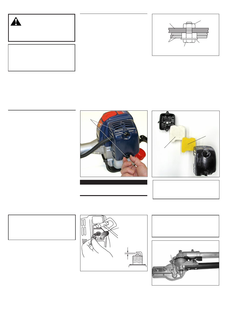
Guide Bar
Locknut
Cutter Blades
Shoulder
Bolt
Washer
(should turn
freely)
Figure 17
Cutter Blade Adjustment
Figure 20
Figure 19
Adjust blades as follows (Figure 17):
1. Loosen all blade locknuts at least one
full turn.
. Tighten each blade shoulder bolt firmly,
and then loosen the shoulder bolts 1/4
to 1/ turn.
3. Working from the gearcase end, lock
each bolt in place by firmly tightening
its locknut while preventing the shoul-
der bolt from turning.
When shoulder bolt adjustment is correct,
there should be a gap of
0.5–0.50 mm between the cutter blades
and the flat washers, and the flat washer
beneath each bolt head should turn freely.
CAUTION!
Overlubricating can cause the gearbox
to operate sluggishly and can cause
grease to leak out.
10-Hour Maintenance
Unscrew
Fasteners
Figure 18A
(more frequently in dusty
conditions)
1. Remove the air cleaner cover by loosen-
ing the thumb screws and lifting up. See
Figure 18A.
. Remove and inspect the pre-filter. If the
pre-filter is torn or otherwise damaged,
replace it with a new one.
See Figure 18B.
3. Clean the pre-filter with soap and water.
Let dry before reinstalling.
4. Inspect the air cleaner element. If the
element is damaged or distorted, re-
place it with a new one.
5. Tap filter gently on a hard surface to
dislodge debris from element or use
compressed air from the inside to blow
debris out and away from the air filter
element.
CAUTION!
Never operate the unit if the air cleaner
assembly is damaged or missing!
IMPORTANT!
Direct the air stream at the inside face of
the filter only!
6. Install the filter element, pre-filter and
cover in the reverse order of removal.
Figure 18B
Filter
Element
Pre-Filter