Sonic Impact Technologies Power 2 User Manual
Page 9
7
Biasing of the Power Tubes
Bias voltage applied to the grids of the power tubes in the output stage should be
checked from time to time (once a month) to keep these tubes operating at the optimum
operating point. A properly biased power tube will have a longer, happier life.
To check the bias of the 6550C/KT88 tubes, place the amplifier in mute with the power
on and the amplifier in operate mode (STANDBY LED Green; Power LED Red-for MUTE).
Looking at the tube top, take note of the power tube location and the bias LED below the
surface of the chassis next to each tube. Also note the printed line that leads to each
power tube. At the opposite end of this line is the bias adjustment for each power tube, a
small slotted metal shaft, again located below the chassis surface. See reference dia-
grams for further clarification.
If a bias LED is glowing red the tube is overbiased; if a bias LED is glowing green the
tube is underbiased, both conditions cause undue wear and/or are not optimal for the
tube. The LED should not be glowing at all for the proper operating bias.
To properly bias the tubes is a simple procedure. For the power tubes on the left (LV5 to
LV8) insert the biasing driver into the slot head of the bias adjustment control and turn
the driver to adjust the control counterclockwise so the LED is green. Turn the adjustment
back clockwise until the LED begins to dim. At this point; through careful adjustment,
continue slowly turning the bias control, stopping the moment the LED goes out. No light
from the LED indicates a properly biased tube. For the most accurate biasing, the
biasing controls should always be rotated from the LED emitting gre e n
to the LED emitting no light, stopping immediately, as soon as the LED
emits no light.
Repeat procedure on the next tube until all tubes are properly biased.
For tubes on the right side of the amplifier (V5 to V8) the biasing controls are opposite.
Turn the biasing controls clockwise initially to decrease bias so the LED is green and
counterclockwise until the LED goes out. Refer to the Tube Top diagram for direction.
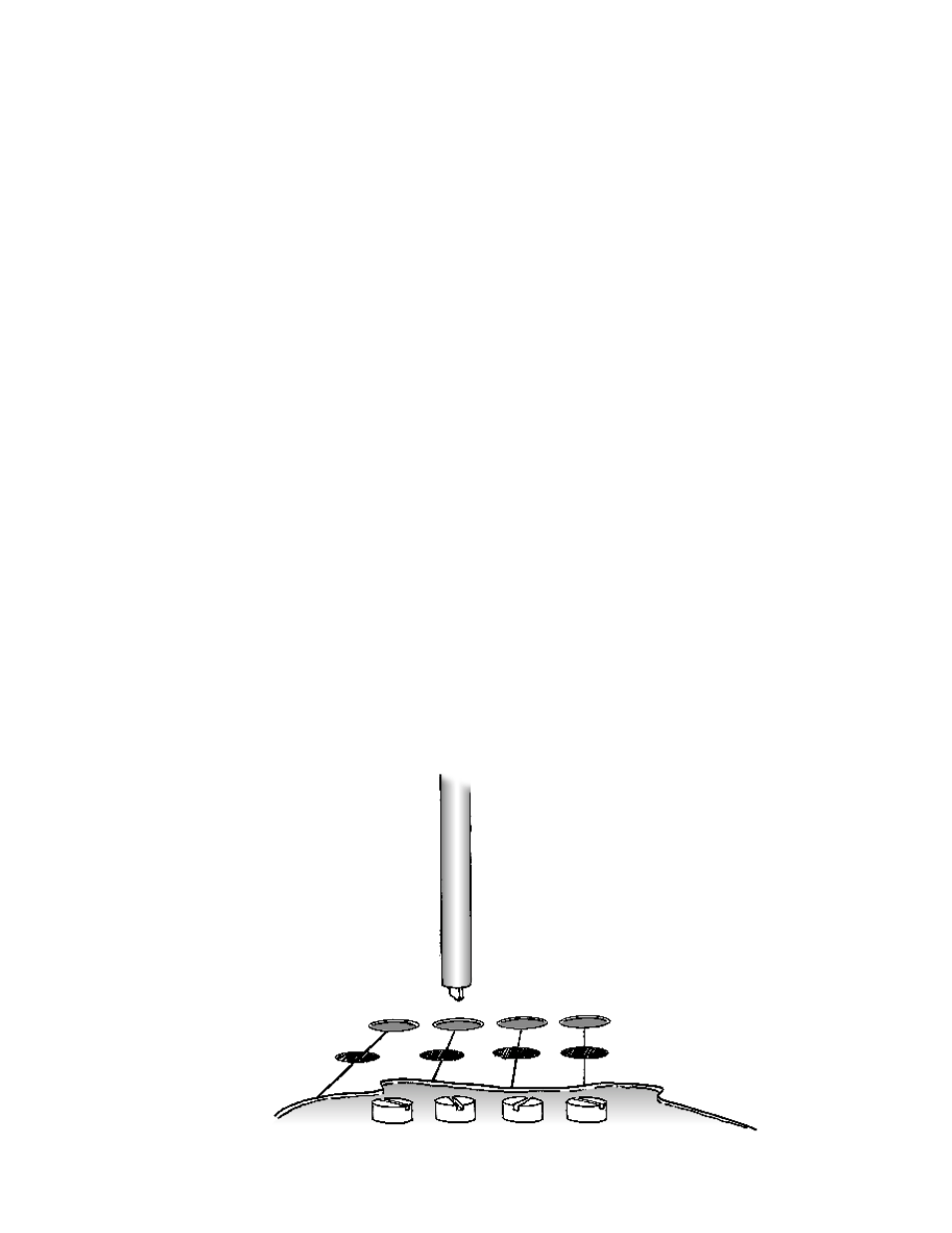
A cutaway of the tube
top showing the location of
the biasing controls below
the tube top surface
and the biasing driver.