Schumacher XC10 User Manual
Page 5
•
4
•
Connect the POSITIVE (RED) charger clip to the POSITIVE (POS, P, +) post of the battery.
7.3
Position yourself and the free end of the cable you previously attached to the NEGATIVE
7.4
(NEG, N, -) battery post as far away from the battery as possible – then connect the
NEGATIVE (BLACK) charger clip to the free end of the cable.
Do not face the battery when making the final connection.
7.5
Connect charger AC supply cord to electrical outlet.
7.6
When disconnecting the charger, always do so in the reverse order of the connecting
7.7
procedure and break the first connection while as far away from the battery as practical.
A marine (boat) battery must be removed and charged on shore. To charge it onboard
7.8
requires equipment specially designed for marine use.
GROUNDING AND AC POWER CORD CONNECTIONS
8.
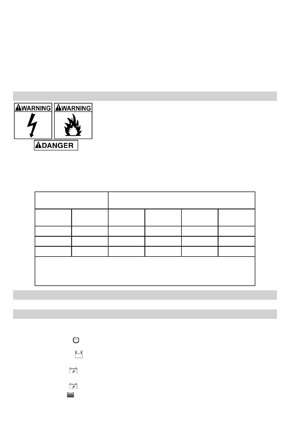
RISK OF ELECTRIC SHOCK OR FIRE.
This battery charger is for use on a nominal 120-volt circuit.
8.1
The plug must be plugged into an outlet that is properly installed
and grounded in accordance with all local codes and ordinances.
The plug pins must fit the receptacle (outlet).
8.2
Never alter the AC cord or plug provided – if it does not fit the
outlet, have a proper grounded outlet installed by a qualified electrician. An improper
connection can result in a risk of an electric shock or electrocution.
NOTE: Pursuant to Canadian Regulations, use of an adapter plug is not allowed in Canada.
Use of an adapter plug in the United States is not recommended and should not be used.
Recommended minimum AWG size for extension cord:
8.3
AC input rating,
amperes*
AWG size of cord
Length of cord, feet (m)
At
least
But less
than
25
(7.6)
50
(15.2)
100
(30.5)
150
(45.6)
0
2
18
18
18
16
2
3
18
18
16
14
3
4
18
18
16
14
*If the input rating of a charger is given in watts rather than in amperes, the
corresponding ampere rating is to be determined by dividing the wattage rating by
the voltage rating - for example:
1200 watts/120 volts = 10 amperes
ASSEMBLY INSTRUCTIONS
9.
Remove all cord wraps and uncoil the cables prior to using the battery charger.
CONTROL PANEL
10.
NOTE: Not all controls are available on all models.
LED Indicators
A.C. POWER (red) LED lit: Indicates that there is AC power supplied to the
battery charger.
CONNECTED
(red) LED lit: Indicates that the charger is properly connected to
the battery.
CHARGING (yellow) LED lit: Indicates the charger has detected a battery and is
charging it.
CHARGING (yellow) LED flashing: Indicates the charger is in abort mode.
CHARGED (green) LED lit: Indicates the battery is fully charged and the charger is
in maintain mode
.
NOTE: See the Operating Instructions section for a complete description of the
charger modes.