Connecting pin assignments, Rs-232c terminal: d-sub 9 pin male connector, Lan terminal: lan (rj-45) – Sharp XG-P610X User Manual
Page 12
-12
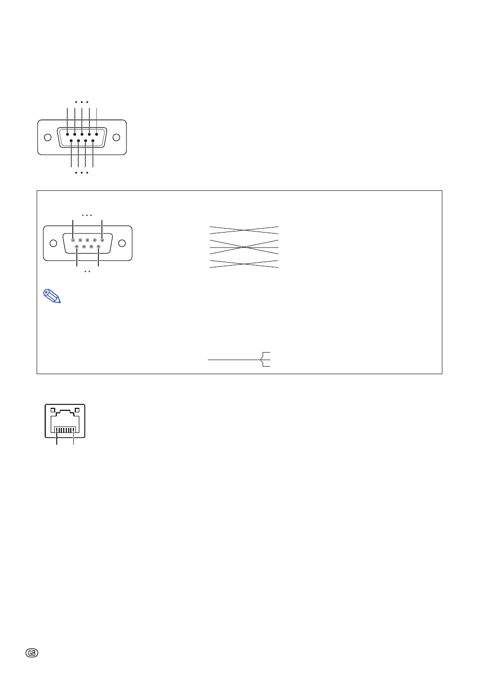
Connecting Pin Assignments
RS-232C Terminal: D-sub 9 pin male connector
Pin No.
Signal
Name
I/O
Reference
1
Not connected
2
RD
Receive Data
Input
Connected to internal circuit
3
SD
Send Data
Output
Connected to internal circuit
4
Not connected
5
SG
Signal Ground
Connected to internal circuit
6
Not connected
7
RS
Request to Send
Connected to CS in internal circuit
8
CS
Clear to Send
Connected to RS in internal circuit
9
Not connected
RS-232C Cable recommended connection: D-sub 9-pin female connector
Pin No.
Signal
Pin No.
Signal
1
CD
1
CD
2
RD
2
RD
3
SD
3
SD
4
ER
4
ER
5
SG
5
SG
6
DR
6
DR
7
RS
7
RS
8
CS
8
CS
9
CI
9
CI
Note
• Depending on the controlling device used, it may be necessary to connect Pin 4 and Pin 6 on the controlling
device (e.g. computer).
LAN Terminal: LAN (RJ-45)
Pin No.
Signal
Pin No.
Signal
1
TX+
5
2
TX–
6
RX–
3
RX+
7
4
8
5
1
9
6
Projector
Pin No.
4
5
6
Computer
Pin No.
4
5
6
5
1
9
6
8 ... 1