Figure 7.1 supply rise time model, 2 recommended operating conditions, Recommended operating conditions – SMSC USB2250i User Manual
Page 29
Ultra Fast USB 2.0 Multi-Slot Flash Media Controller
Datasheet
SMSC USB2250/50i/51/51i
29
Revision 1.1 (05-29-08)
DATASHEET
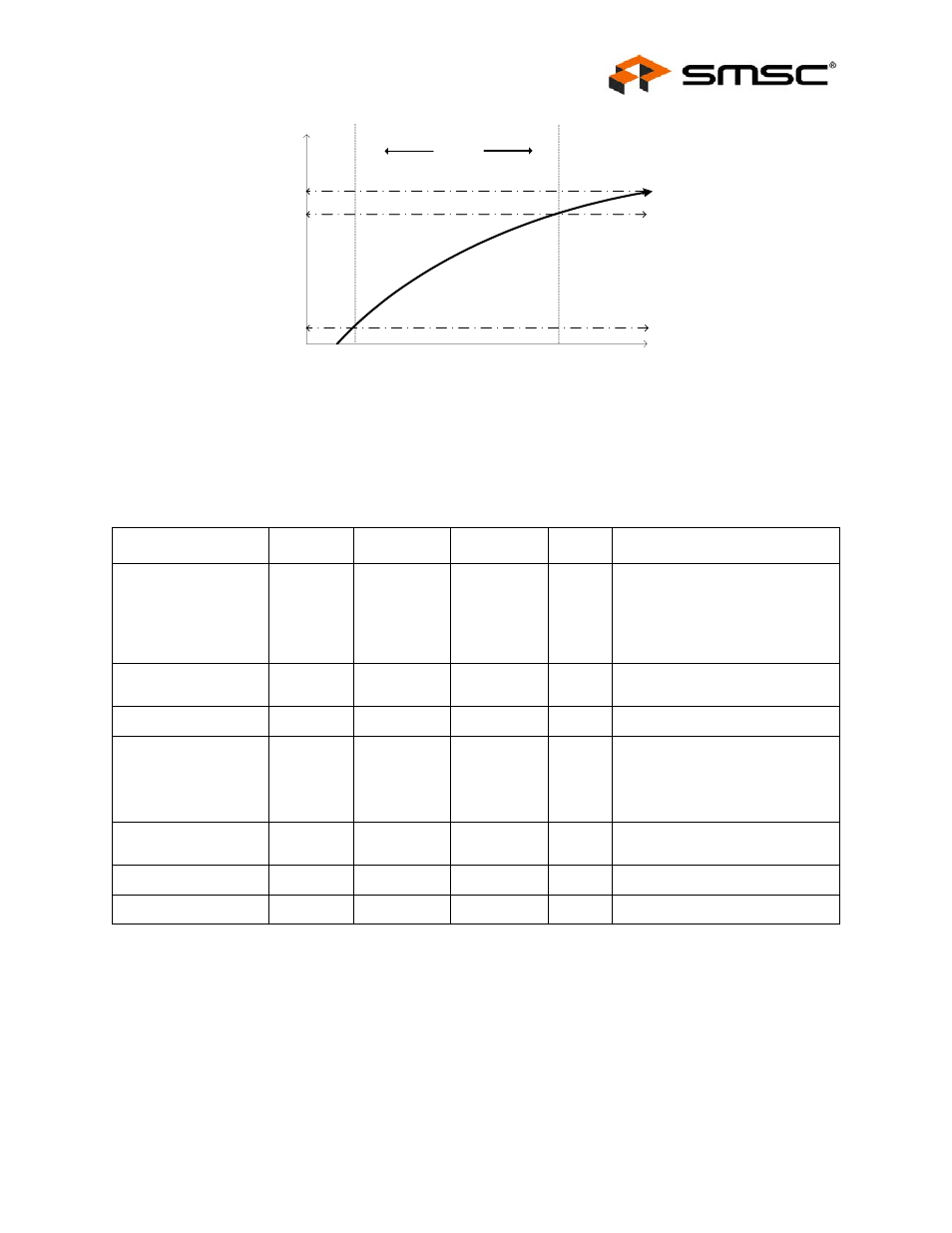
Figure 7.1 Supply Rise Time Model
Note 7.3
When powering the device, the maximum power supply ramp time should be set at a rate
faster than 400
μs. This speed is important to ensure that the device resets properly.
Measure rise time at 10% and 90%.
7.2
Recommended Operating Conditions
Note 7.4
A 3.3V regulator with an output tolerance of 1% must be used if the output of the internal
power FET’s must support a 5% tolerance.
PARAMETER
SYMBOL
MIN
MAX
UNITS
COMMENTS
Operating
Temperature
Commercial Part
Industrial Part
T
A
T
A
0
-40
70
85
°C
°C
3.3V supply voltage
V
DD33,
V
DDA33
3.0
3.6
V
(
3.3V supply rise time
t
RT
0
400
)
Voltage on
USB+ and USB- pins
-0.3
5.5
V
If any 3.3V supply voltage drops
below 3.0V, then the MAX
becomes:
(3.3V supply voltage) + 0.5
≤ 5.5
Voltage on any signal
pin
-0.3
V
DD33
V
Voltage on XTAL1
-0.3
V
DDA33
V
Voltage on XTAL2
-0.3
V
DD18
V
t
10%
10%
90%
Voltage
t
RT
t
90%
Time
100%
3.3V
VSS
VDD33