Sony FD Trinitron KV-21LT1E User Manual
Page 12
12
SECTION 2
DISASSEMBLY
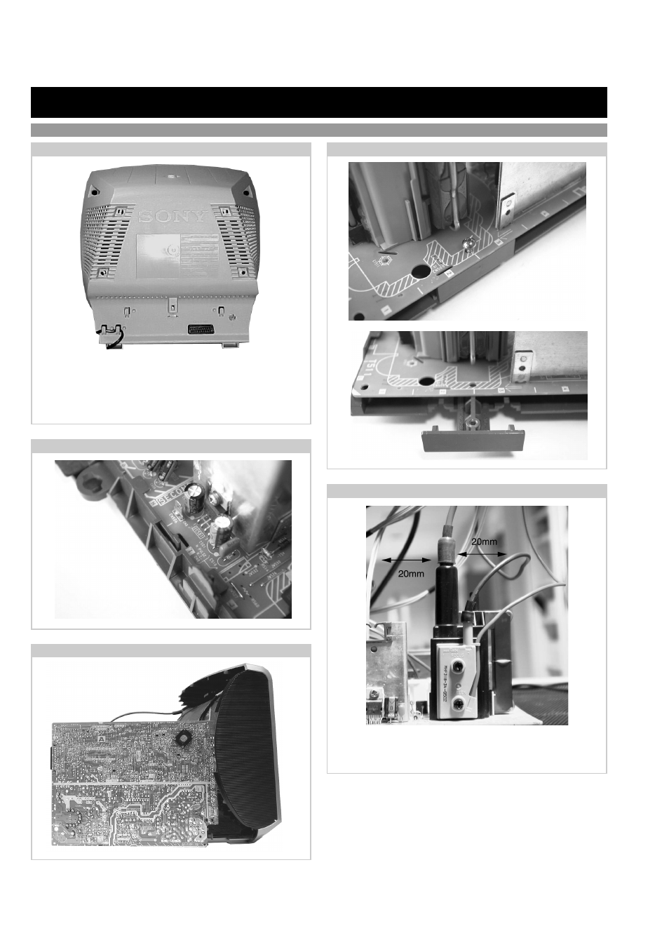
2-3. A Board PWB Removal [ Step 2 ]
2-2. A Board PWB Removal [ Step 1 ]
2-5. Wire Dressing
Ensure that all wires do not touch heat-sinks and high
temperature hot spots. All wires must be kept at a minimum
distance of 20mm away from the EHT lead.
2-1. Rear Cover Removal
2-4. Service Position
Release the mains power cable from its securing posts.
Remove the rear cover fixing screws indicated. Pull the rear
cover away from the front beznet until clear of chassis.
Note : Use a cross-head screwdriver with a blade length of at
least 200mm.
KV-21LT1
Remove screw.
<=
Remove FBT
support bracket.
<=
Release the 2 securing
clips located at either
side of the chassis and
slide the PWB clear of
the bracket.
<=
Place the A Board PWB in the
position indicated to carry out
servicing.
=>
=>
<=
<=
- KLV-23HR2 (1 page)
- KLV-21SR2 (1 page)
- KLV-23M1 (1 page)
- KLV-23HR2 (84 pages)
- KV-29LS35K (122 pages)
- KV-14CT1K (128 pages)
- FD Trinitron KV-29XL71K (124 pages)
- KLV-15SR1 (88 pages)
- KE-P37M1 (204 pages)
- KLV-21SR2 (60 pages)
- KV-34FQ75K (160 pages)
- KZ-32TS1E (135 pages)
- KLV-23HR3 (134 pages)
- FD Trinitron KV-29CL10K (122 pages)
- FD Trinitron KV-29XL70K (124 pages)
- KV-32HQ150K (148 pages)
- KLV-15SR1 (28 pages)
- KLV-15SR1 (1 page)
- KLV-15SR1 (1 page)
- KLV-15SR1 (2 pages)
- KV-14LT1K (128 pages)
- FD Trinitron KV-29LS30K (116 pages)
- KE-32TS2E (135 pages)
- KV-32FX68K (124 pages)
- KE-42MR1 (305 pages)
- KV-21LS30K (116 pages)
- KP-44PX2 (146 pages)
- WEGA KLV-30MR1 (304 pages)
- KLV-21SG2 (1 page)
- KLV-26HG2 (84 pages)
- KDL-32XBR950 (64 pages)
- KLV-26HG2 (1 page)
- KLV-21SG2 (292 pages)
- KV-21FX30K (135 pages)
- KDL-40X2000 (160 pages)
- FD Trinitron KV-32FQ70K (146 pages)
- KV-29FQ65K (160 pages)
- FD Trinitron WEGA KV-32CS71K (144 pages)
- KDL-40X2000 (160 pages)
- KV-29FQ85K (164 pages)
- KV-29FQ75K (160 pages)
- KV-21CL10K (128 pages)
- KDL-40V2500 (2 pages)
- KDL-40V2500 (48 pages)
- KDL-46V2500 (2 pages)