Scotts Automobile Parts User Manual
Page 10
6
Rack
(1) M
(2) Ra
(2)5/8
(2) 5/
(2) 5/
(2) Ou
(2) Ra
1
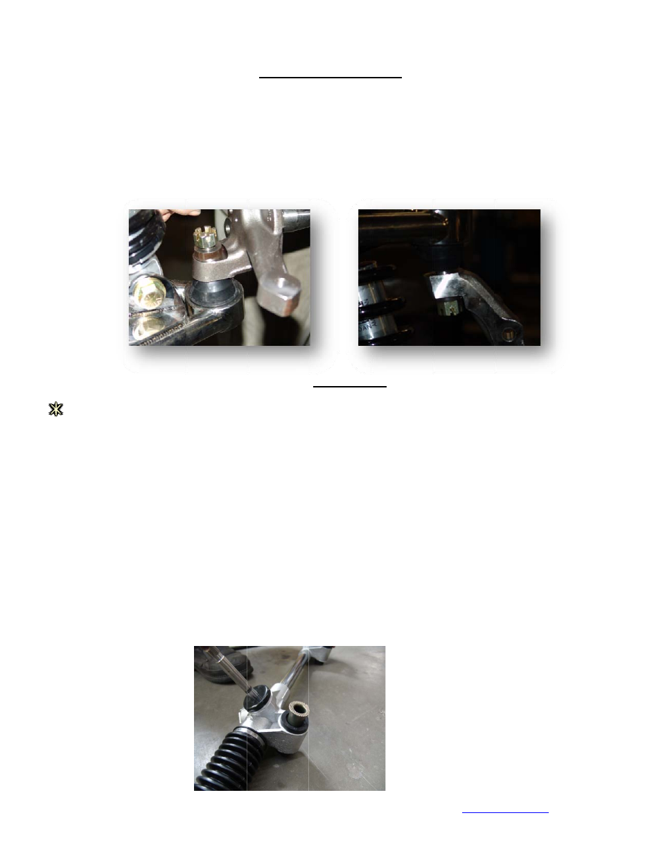
6. To install t
joints), (2)
coil‐over s
driver’s sid
joint nut b
spindle on
Rack assembly
components
Manual rack
ack bushings &
8‐18x3‐1/2” gr
/8” USS flat wa
/8” Nuts
uter tie‐rod en
ack extensions
1. Begin by as
ends to the
Rev
he spindles yo
3/16” ball‐join
hock, placeme
de spindle onto
ack in place an
ly you will use
y will be the sa
rack, you
s:
& sleeves
rade 8 yellow b
ashers
nds
(optional)
If you are uns
ssembling you
e rack.
v: A Installation M
u will need (2)
nt spacers, and
ent of the spind
o the driver’s s
nd tighten. Rep
the 3/16 spac
ame whether y
may have rece
bolts
sure whether o
r rack. Insert t
anual for Standard
A‐Arm spin
) spindles, one
d (2) 3/8” ball‐j
dle to the lowe
ide lower a‐arm
peat this step f
er rather than
your kit came w
eived a manua
or not you have
the Rack bushi
d front steer IFS
ndle assembl
left, one right,
oint spacers.
er a‐arm is mad
m. Place the 3
for passenger
the 3/8.
Rack Assem
with a power o
l rack but still f
e these, check
ngs and sleeve
ly cont
, (4) ball‐joint c
Because the lo
de easy. Simpl
3/8” ball joint s
side. The uppe
mbly
or manual rack
follow the inst
your packing s
es into the rack
castle nuts (the
ower a‐arm is lo
y remove the
spacer on the b
ers arm is insta
. Although the
ructions as wr
slip.
k. (insert photo
www.sco
ese are still on
ocked into pla
ball joint nut a
ball joint and p
alled the same
ese examples s
itten.
o) Thread the o
ottshotrods.com
n the ball
ce with the
and place the
place the ball
e way into the
show a power
out tie rod